2004 SUBARU FORESTER light
[x] Cancel search: lightPage 230 of 2870

AB-98
AIRBAG SYSTEM (DIAGNOSTIC)
Diagnostic Procedure with Diagnostic Trouble Code (DTC)
Step Check Yes No
1 CHECK LAP SEAT BELT PRETENSIONER.
1) Turn the ignition switch to OFF, disconnect
the battery ground cable, and wait more than
20 seconds.
2) Disconnect the connector (AB25) from the
lap seat belt pretensioner (RH).
3) Connect the connector (1Q) in test harness
Q to (AB25).
4) Connect the airbag resistor to connector
(2Q) in test harness Q.
5) Connect the battery ground cable, and turn
the ignition switch to ON.Is the airbag warning light
turned on normally?Replace the lap
seat belt preten-
sioner (RH).
OUTER SEAT
BELT WITH LAP
SEAT BELT PRE-
TENSIONER,
REMOVAL, Front
Seat Belt.>Go to step 2.
2 CHECK SIDE AIRBAG HARNESS (RH).
1) Turn the ignition switch to OFF, disconnect
the battery ground cable, and wait more than
20 seconds.
2) Disconnect the airbag resistor from the test
harness.
3) Disconnect the connector (AB11) from side
airbag module (RH).
4) Disconnect the connectors (AB20) from
seat belt pretensioner.
5) Disconnect the connector (AB8) from air-
bag control module.
6) Connect the connector (1R) in test harness
R to the connector (AB8).
7) Measure the resistance between connector
(3R) in test harness R and connector (2Q) in
test harness Q.
Connector & terminal
(3R) No. 2 — (2Q) No. 2:
(3R) No. 4 — (2Q) No. 1: Is the resistance less than 10
Ω?Go to step 3.Replace the side
airbag harness
with body harness.
3 CHECK SIDE AIRBAG HARNESS.
Measure the resistance between the connector
(3R) in test harness R and the chassis ground.
Connector & terminal
(3R) No. 2 — (3R) No. 4:
(3R) No. 2 — Chassis ground:
(3R) No. 4 — Chassis ground: Is the resistance more than 1
MΩ?Replace the airbag
control module.
Module.>Replace the side
airbag harness
with body harness.
Page 231 of 2870

AB-99
AIRBAG SYSTEM (DIAGNOSTIC)
Diagnostic Procedure with Diagnostic Trouble Code (DTC)
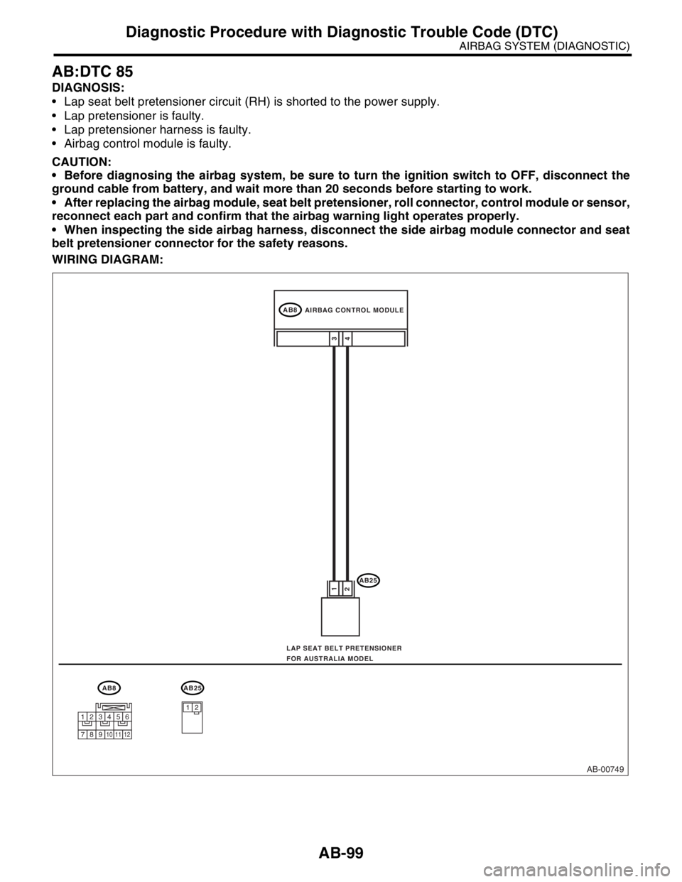
AB:DTC 85
DIAGNOSIS:
Lap seat belt pretensioner circuit (RH) is shorted to the power supply.
Lap pretensioner is faulty.
Lap pretensioner harness is faulty.
Airbag control module is faulty.
CAUTION:
Before diagnosing the airbag system, be sure to turn the ignition switch to OFF, disconnect the
ground cable from battery, and wait more than 20 seconds before starting to work.
After replacing the airbag module, seat belt pretensioner, roll connector, control module or sensor,
reconnect each part and confirm that the airbag warning light operates properly.
When inspecting the side airbag harness, disconnect the side airbag module connector and seat
belt pretensioner connector for the safety reasons.
WIRING DIAGRAM:
AB-00749
AB8
AB25
4 1
23
AB8AB25
12
AIRBAG CONTROL MODULE
LAP SEAT BELT PRETENSIONER
FOR AUSTRALIA MODEL
123456
789101112
Page 232 of 2870

AB-100
AIRBAG SYSTEM (DIAGNOSTIC)
Diagnostic Procedure with Diagnostic Trouble Code (DTC)
Step Check Yes No
1 CHECK LAP SEAT BELT PRETENSIONER.
1) Turn the ignition switch to OFF, disconnect
the battery ground cable, and wait more than
20 seconds.
2) Disconnect the connector (AB25) from the
lap seat belt pretensioner (RH).
3) Connect the connector (1Q) in test harness
Q to (AB25).
4) Connect the airbag resistor to the connec-
tor (2Q) in test harness Q.
5) Connect the battery ground cable and turn
the ignition switch to ON.Is the airbag warning light
turned on normally?Replace the lap
seat belt preten-
sioner (RH).
OUTER SEAT
BELT WITH LAP
SEAT BELT PRE-
TENSIONER,
REMOVAL, Front
Seat Belt.>Go to step 2.
2 CHECK SIDE AIRBAG HARNESS (RH).
1) Turn the ignition switch to OFF, disconnect
the battery ground cable, and wait more than
20 seconds.
2) Disconnect the airbag resistor from the test
harness.
3) Disconnect the connector (AB11) from side
airbag module (RH).
4) Disconnect the connector (AB20) from seat
belt pretensioner.
5) Disconnect the connectors (AB7) and
(AB8) from the airbag control module.
6) Connect the connector (1R) in test harness
R to the connector (AB7).
7) Connect the battery ground cable and turn
the ignition switch to ON.
8) Measure the voltage between connector
(3R) in test harness R and the chassis ground.
Connector & terminal
(3R) No. 2 (+) — Chassis ground (
−):
(3R) No. 4 (+) — Chassis ground (
−): Is the voltage less than 1 V? Replace the airbag
control module.
Module.>Replace the side
airbag harness
with body harness.
Page 233 of 2870

FUJI HEAVY INDUSTRIES LTD. G8080GE7
2004 FORESTER SERVICE MANUAL QUICK REFERENCE INDEX
BODY SECTION
This service manual has been prepared
to provide SUBARU service personnel
with the necessary information and data
for the correct maintenance and repair
of SUBARU vehicles.
This manual includes the procedures
for maintenance, disassembling, reas-
sembling, inspection and adjustment of
components and diagnostics for guid-
ance of experienced mechanics.
Please peruse and utilize this manual
fully to ensure complete repair work for
satisfying our customers by keeping
their vehicle in optimum condition.
When replacement of parts during
repair work is needed, be sure to use
SUBARU genuine parts.
All information, illustration and specifi-
cations contained in this manual are
based on the latest product information
available at the time of publication
approval.HVAC SYSTEM
(HEATER, VENTILATOR AND A/C)AC
HVAC SYSTEM (AUTO A/C)
(DIAGNOSTIC)AC
AIRBAG SYSTEM AB
AIRBAG SYSTEM (DIAGNOSTIC) AB
SEAT BELT SYSTEM SB
LIGHTING SYSTEM LI
WIPER AND WASHER SYSTEM WW
ENTERTAINMENT ET
COMMUNICATION SYSTEM COM
GLASS/WINDOW/MIRROR GW
BODY STRUCTURE BS
INSTRUMENTATION/DRIVER INFO IDI
SEAT SE
SECURITY AND LOCK SL
SUNROOF/T-TOP/CONVERTIBLE TOP
(SUNROOF)SR
EXTERIOR/INTERIOR TRIM EI
EXTERIOR BODY PANEL EB
Page 241 of 2870

SB-7
SEAT BELT SYSTEM
Seat Belt Warning System
3. Seat Belt Warning System
A: WIRING DIAGRAM
B: INSPECTION
TROUBLE SYMPTOM:
Seat belt warning light does not come on or go off.
Buzzer does not beep.
Step Check Yes No
1 CHECK HARNESS BETWEEN SEAT BELT
TIMER MODULE AND CHASSIS GROUND.
1) Turn the ignition switch to OFF.
2) Disconnect the connector from seat belt
timer module.
3) Measure the resistance between seat belt
timer module harness connector and chassis
ground.
Connector & terminal
(B44) No. 3 — Chassis ground:Is the resistance less than 1
Ω?Go to step 2.Repair the open
circuit of harness
between seat belt
timer module and
chassis ground.
2 CHECK POWER SUPPLY OF SEAT BELT
TIMER MODULE.
1) Turn the ignition switch to ON.
2) Measure the voltage between seat belt
timer module connector and chassis ground.
Connector & terminal
(B44) No. 9 (+) — Chassis ground (–):Is the voltage more than 10 V? Go to step 3.Repair the open
harness, short cir-
cuit and poor con-
tact of connector
between seat belt
timer module and
battery.
3 CHECK HARNESS AND SEAT BELT
SWITCH.
1) Turn the ignition switch to OFF.
2) Disconnect the connector from seat belt
timer module.
3) Hold the tang plate disconnected from seat
belt buckle.
4) Measure the resistance between seat belt
timer module harness connector and chassis
ground.
Connector & terminal
(B44) No. 6 — Chassis ground:Is the resistance less than 1
Ω?Go to step 4.Repair the short
circuit of harness
between seat belt
timer module con-
nector and chassis
ground.
4 CHECK SEAT BELT SWITCH AND HAR-
NESS.
1) Turn the ignition switch to OFF.
2) Insert the tang plate into seat belt buckle.
3) Measure the resistance between seat belt
timer module connector and chassis ground.
Connector & terminal
(B44) No. 6 — Chassis ground:Is the resistance more than 1
MΩ?Go to step 7.Go to step 5.
5 CHECK HARNESS BETWEEN SEAT BELT
TIMER MODULE AND SEAT BELT SWITCH.
Measure the resistance of harness between
seat belt timer module connector and seat belt
switch.
Connector & terminal
(B44) No. 6 — (R8) No. 2:Is the resistance less than 1
Ω?Go to step 6.Repair the open
circuit of harness
and poor contact
of connector
between seat belt
timer module con-
nector and seat
belt switch.
Page 243 of 2870

SB-9
SEAT BELT SYSTEM
Seat Belt Warning System
14 CHECK HARNESS BETWEEN TCU AND
SEAT BELT TIMER MODULE.
Measure the resistance between seat belt
timer module harness connector and chassis
ground.
Connector & terminal
(B44) No. 7 — Chassis ground:Is the resistance less than 10
Ω?Go to step 15.Repair the short of
harness.
15 CHECK SEAT BELT TIMER MODULE OUT-
PUT SIGNAL.
1) Turn the ignition switch to ON.
2) Measure the voltage between seat belt
timer module harness connector and chassis
ground.
Connector & terminal
(B44) No. 2 (+) — Chassis ground (–):Is the voltage more than 10 V? Go to step 16.Check the wiring
harness and com-
bination meter,
and then repair or
replace them.
16 CHECK POOR CONTACT.
Check the poor contact of seat belt warning
light circuit.Is there any poor contact
occurs?Repair the poor
contact.Go to step 17.
17 CHECK SEAT BELT TIMER MODULE.
1) Connect all connectors.
2) Lift-up the vehicle and place rigid racks.
NOTE:
Raise all wheels off floor.
3) Hold the tang plate disconnected from seat
belt buckle.
4) Start the engine, and set the vehicle speed
less than 19 km/h (12 MPH)
N
OTE:
The speed difference between front and rear
wheels may light the ABS warning light, but this
indicates no malfunction. When diagnosis is fin-
ished, perform the ABS memory clearance pro-
cedure of OBD system.
Check seat belt warning light comes on.Does the seat belt warning
light come on?Go to step 18.Replace the seat
belt timer module.
18 CHECK SEAT BELT TIMER MODULE.
1) Connect all connectors.
2) Lift-up the vehicle and place rigid racks.
N
OTE:
Raise all wheels off floor.
3) Hold the tang plate disconnected from seat
belt buckle.
4) Start the engine, and set the vehicle speed
more than 25 km/h (16 MPH).
NOTE:
The speed difference between front and rear
wheels may light the ABS warning light, but this
indicates no malfunction. When diagnosis is fin-
ished, perform the ABS memory clearance pro-
cedure of OBD system.
Check seat belt warning light comes on and
buzzer beeps.Does the seat belt warning
light come on and buzzer
beep?Temporary poor
contact of connec-
tor or harness may
be the cause.
Check the poor
contact.Replace the seat
belt timer module. Step Check Yes No
Page 253 of 2870

FUJI HEAVY INDUSTRIES LTD. G8080GE7
2004 FORESTER SERVICE MANUAL QUICK REFERENCE INDEX
BODY SECTION
This service manual has been prepared
to provide SUBARU service personnel
with the necessary information and data
for the correct maintenance and repair
of SUBARU vehicles.
This manual includes the procedures
for maintenance, disassembling, reas-
sembling, inspection and adjustment of
components and diagnostics for guid-
ance of experienced mechanics.
Please peruse and utilize this manual
fully to ensure complete repair work for
satisfying our customers by keeping
their vehicle in optimum condition.
When replacement of parts during
repair work is needed, be sure to use
SUBARU genuine parts.
All information, illustration and specifi-
cations contained in this manual are
based on the latest product information
available at the time of publication
approval.HVAC SYSTEM
(HEATER, VENTILATOR AND A/C)AC
HVAC SYSTEM (AUTO A/C)
(DIAGNOSTIC)AC
AIRBAG SYSTEM AB
AIRBAG SYSTEM (DIAGNOSTIC) AB
SEAT BELT SYSTEM SB
LIGHTING SYSTEM LI
WIPER AND WASHER SYSTEM WW
ENTERTAINMENT ET
COMMUNICATION SYSTEM COM
GLASS/WINDOW/MIRROR GW
BODY STRUCTURE BS
INSTRUMENTATION/DRIVER INFO IDI
SEAT SE
SECURITY AND LOCK SL
SUNROOF/T-TOP/CONVERTIBLE TOP
(SUNROOF)SR
EXTERIOR/INTERIOR TRIM EI
EXTERIOR BODY PANEL EB
Page 255 of 2870

LIGHTING SYSTEM
LI
Page
1. General Description ....................................................................................2
2. Headlight and Tail Light System .................................................................3
3. Front Fog Light System ...............................................................................4
4. Rear Fog Light System ...............................................................................5
5. Turn Signal Light and Hazard Light System................................................6
6. Back-up Light System .................................................................................7
7. Stop Light System .......................................................................................8
8. Room Light System .....................................................................................9
9. Headlight Beam Leveler System ...............................................................10
10. Combination Switch (Light) .......................................................................11
11. Headlight Assembly ..................................................................................13
12. Headlight Bulb ...........................................................................................16
13. Front Turn Signal Light Bulb .....................................................................17
14. Clearance Light Bulb .................................................................................18
15. Front Fog Light Assembly .........................................................................19
16. Front Fog Light Bulb..................................................................................20
17. Rear Combination Light Assembly ............................................................21
18. Tail/Stop Light Bulb ...................................................................................22
19. Back-up Light Bulb ....................................................................................23
20. Rear Turn Signal Light Bulb ......................................................................24
21. Rear Fog Light Bulb ..................................................................................25
22. License Plate Light ....................................................................................26
23. High-mounted Stop Light ..........................................................................27
24. Side Turn Signal Light ...............................................................................28
25. Spot Map Light ..........................................................................................29
26. Room Light ................................................................................................30
27. Luggage Room Light .................................................................................31
28. Glove Box Light .........................................................................................32