Page 2374 of 2870
4AT-61
AUTOMATIC TRANSMISSION
Control Valve Body
17.Control Valve Body
A: REMOVAL
1. NON-TURBO MODEL
1) Lift-up the vehicle.
2) Clean the transmission exterior.
3) Drain the ATF completely.
NOTE:
Tighten the drain plug (ATF) after draining the
ATF.
Always use new gasket.
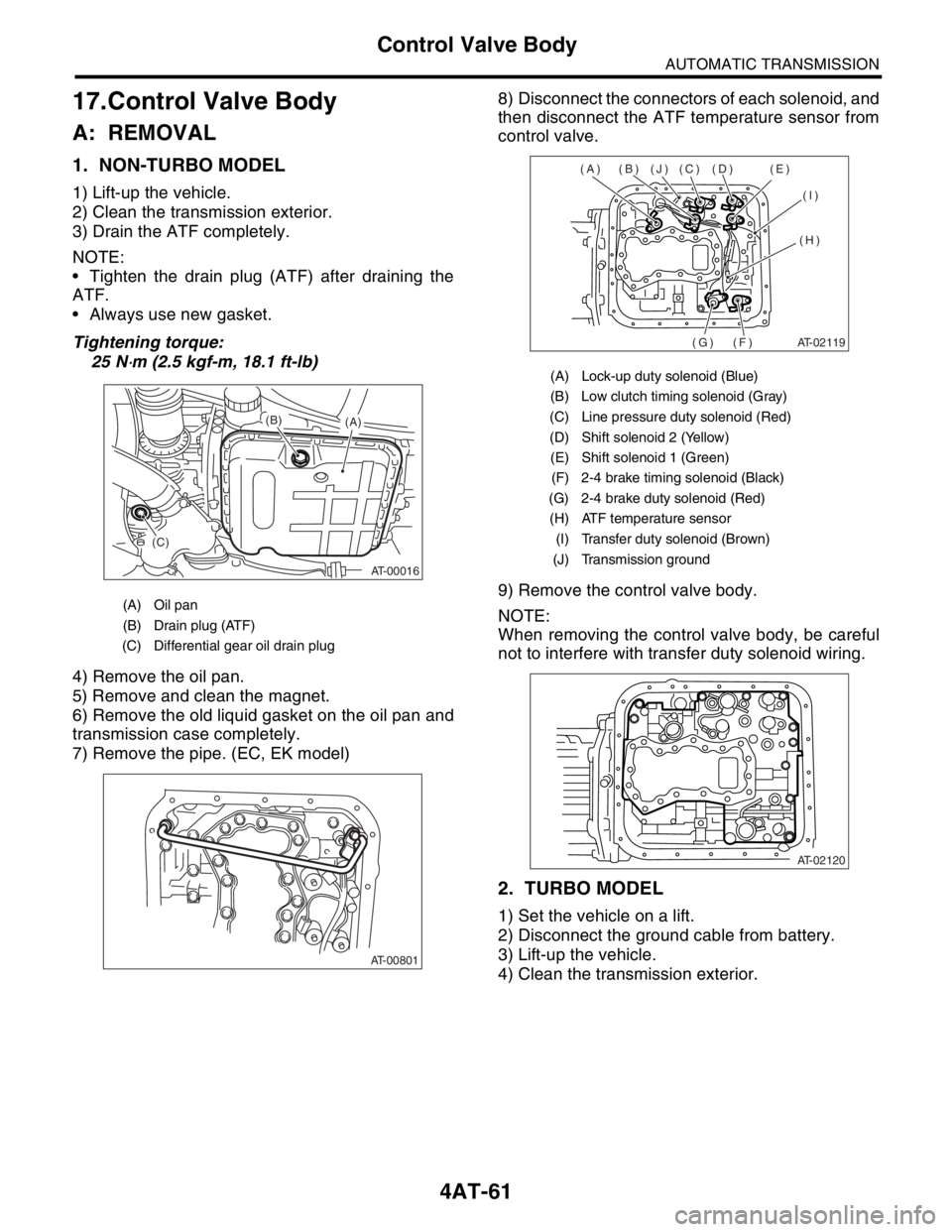
Tightening torque:
25 N
⋅m (2.5 kgf-m, 18.1 ft-lb)
4) Remove the oil pan.
5) Remove and clean the magnet.
6) Remove the old liquid gasket on the oil pan and
transmission case completely.
7) Remove the pipe. (EC, EK model)8) Disconnect the connectors of each solenoid, and
then disconnect the ATF temperature sensor from
control valve.
9) Remove the control valve body.
NOTE:
When removing the control valve body, be careful
not to interfere with transfer duty solenoid wiring.
2. TURBO MODEL
1) Set the vehicle on a lift.
2) Disconnect the ground cable from battery.
3) Lift-up the vehicle.
4) Clean the transmission exterior.
(A) Oil pan
(B) Drain plug (ATF)
(C) Differential gear oil drain plug
AT-00016
(A) (B)
(C)
AT-00801
(A) Lock-up duty solenoid (Blue)
(B) Low clutch timing solenoid (Gray)
(C) Line pressure duty solenoid (Red)
(D) Shift solenoid 2 (Yellow)
(E) Shift solenoid 1 (Green)
(F) 2-4 brake timing solenoid (Black)
(G) 2-4 brake duty solenoid (Red)
(H) ATF temperature sensor
(I) Transfer duty solenoid (Brown)
(J) Transmission ground
AT-02119
(A) (B) (J) (C) (D) (E)
(I)
(H)
(F) (G)
AT-02120
Page 2386 of 2870
4AT-73
AUTOMATIC TRANSMISSION
Transfer Duty Solenoid and Valve Body
20.Transfer Duty Solenoid and
Valve Body
A: REMOVAL
1) Set the vehicle on a lift.
2) Disconnect the ground cable from battery.
3) Remove the air cleaner case. (Non-turbo mod-
el).
Case.>
4) Remove the intercooler. (Turbo model)
er.>
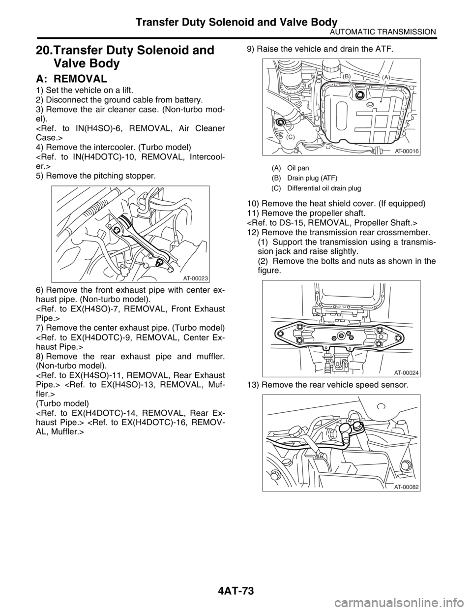
5) Remove the pitching stopper.
6) Remove the front exhaust pipe with center ex-
haust pipe. (Non-turbo model).
Pipe.>
7) Remove the center exhaust pipe. (Turbo model)
haust Pipe.>
8) Remove the rear exhaust pipe and muffler.
(Non-turbo model).
Pipe.>
fler.>
(Turbo model)
haust Pipe.>
AL, Muffler.>9) Raise the vehicle and drain the ATF.
10) Remove the heat shield cover. (If equipped)
11) Remove the propeller shaft.
12) Remove the transmission rear crossmember.
(1) Support the transmission using a transmis-
sion jack and raise slightly.
(2) Remove the bolts and nuts as shown in the
figure.
13) Remove the rear vehicle speed sensor.
AT-00023
(A) Oil pan
(B) Drain plug (ATF)
(C) Differential oil drain plug
AT-00016
(A) (B)
(C)
AT-00024
AT-00082
Page 2410 of 2870
FUJI HEAVY INDUSTRIES LTD. G8080GE5
2004 FORESTER SERVICE MANUAL QUICK REFERENCE INDEX
TRANSMISSION SECTION
This service manual has been prepared
to provide SUBARU service personnel
with the necessary information and data
for the correct maintenance and repair
of SUBARU vehicles.
This manual includes the procedures
for maintenance, disassembling, reas-
sembling, inspection and adjustment of
components and diagnostics for guid-
ance of experienced mechanics.
Please peruse and utilize this manual
fully to ensure complete repair work for
satisfying our customers by keeping
their vehicle in optimum condition.
When replacement of parts during
repair work is needed, be sure to use
SUBARU genuine parts.
All information, illustration and specifi-
cations contained in this manual are
based on the latest product information
available at the time of publication
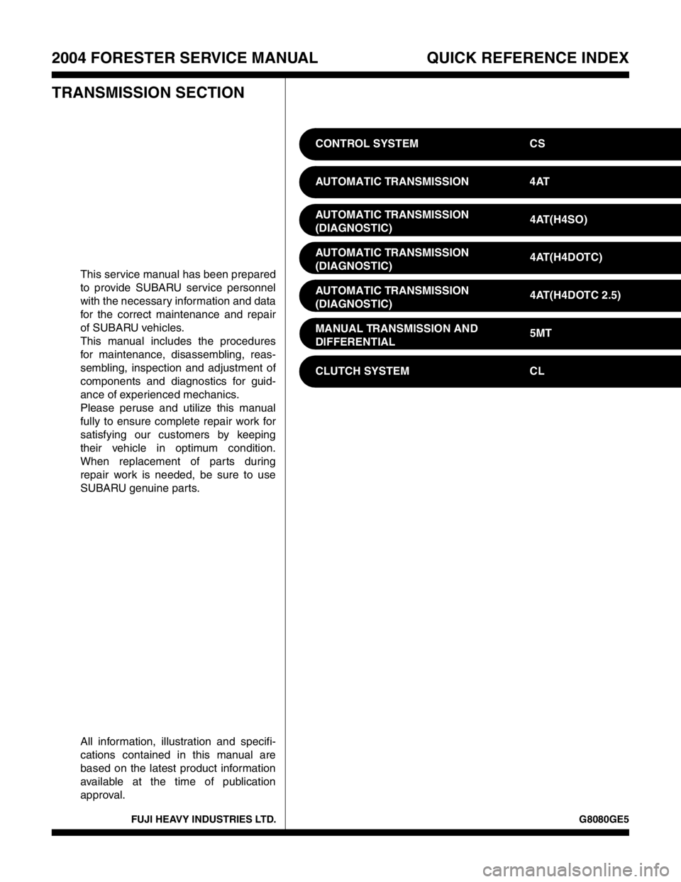
approval.CONTROL SYSTEM CS
AUTOMATIC TRANSMISSION 4AT
AUTOMATIC TRANSMISSION
(DIAGNOSTIC)4AT(H4SO)
AUTOMATIC TRANSMISSION
(DIAGNOSTIC)4AT(H4DOTC)
AUTOMATIC TRANSMISSION
(DIAGNOSTIC)4AT(H4DOTC 2.5)
MANUAL TRANSMISSION AND
DIFFERENTIAL5MT
CLUTCH SYSTEM CL
Page 2416 of 2870
4AT-102
AUTOMATIC TRANSMISSION
Torque Converter Clutch Case
34.Torque Converter Clutch
Case
A: REMOVAL
1) Remove the transmission assembly from vehi-
cle.
mission Assembly.>
2) Pull out the torque converter clutch assembly.
Clutch Assembly.>
3) Remove the input shaft.
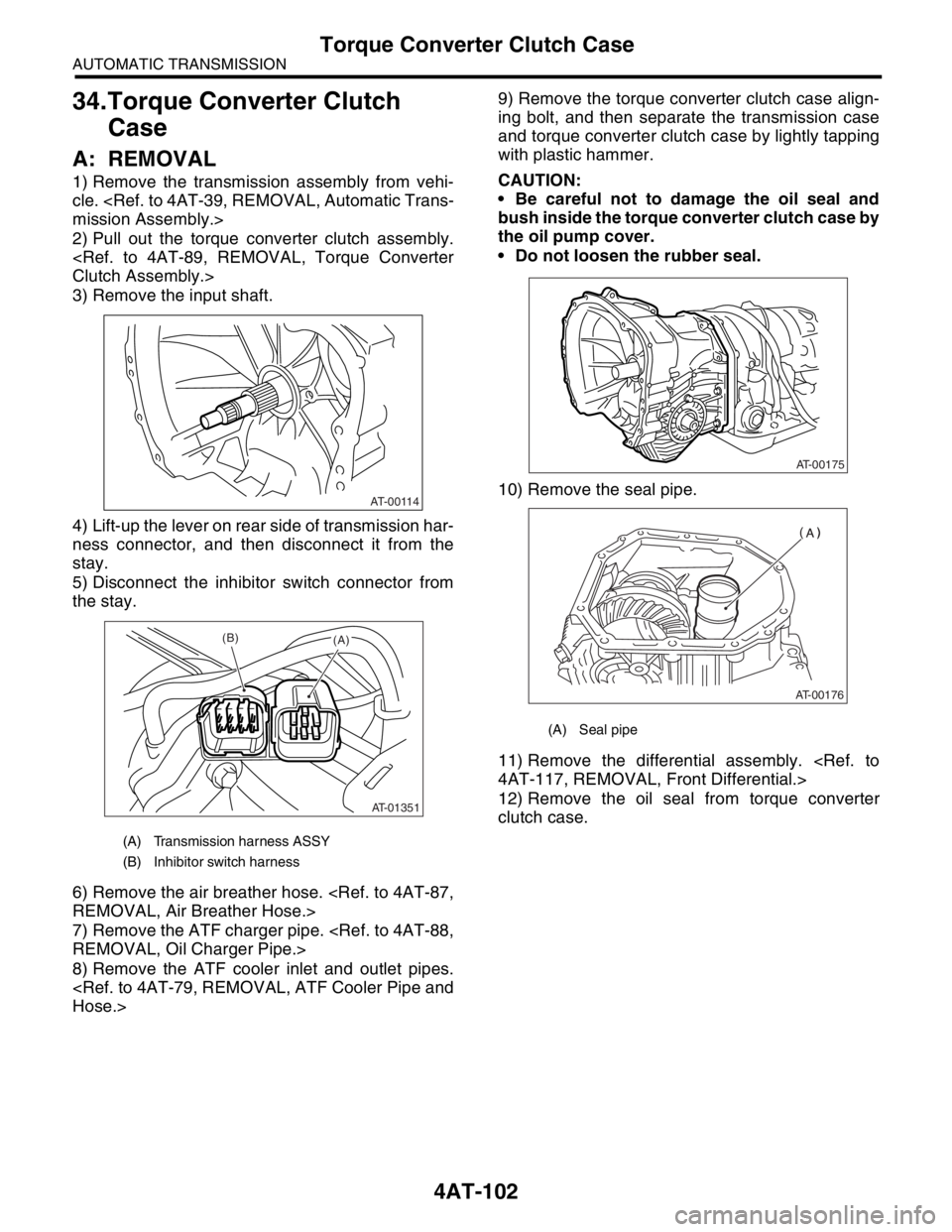
4) Lift-up the lever on rear side of transmission har-
ness connector, and then disconnect it from the
stay.
5) Disconnect the inhibitor switch connector from
the stay.
6) Remove the air breather hose.
REMOVAL, Air Breather Hose.>
7) Remove the ATF charger pipe.
REMOVAL, Oil Charger Pipe.>
8) Remove the ATF cooler inlet and outlet pipes.
Hose.>9) Remove the torque converter clutch case align-
ing bolt, and then separate the transmission case
and torque converter clutch case by lightly tapping
with plastic hammer.
CAUTION:
Be careful not to damage the oil seal and
bush inside the torque converter clutch case by
the oil pump cover.
Do not loosen the rubber seal.
10) Remove the seal pipe.
11) Remove the differential assembly.
4AT-117, REMOVAL, Front Differential.>
12) Remove the oil seal from torque converter
clutch case.
(A) Transmission harness ASSY
(B) Inhibitor switch harness
AT-00114
AT-01351
(B)(A)
(A) Seal pipe
AT-00175
AT-00176
Page 2417 of 2870
4AT-103
AUTOMATIC TRANSMISSION
Torque Converter Clutch Case
B: INSTALLATION
1) Check the appearance of each component and
clean them.
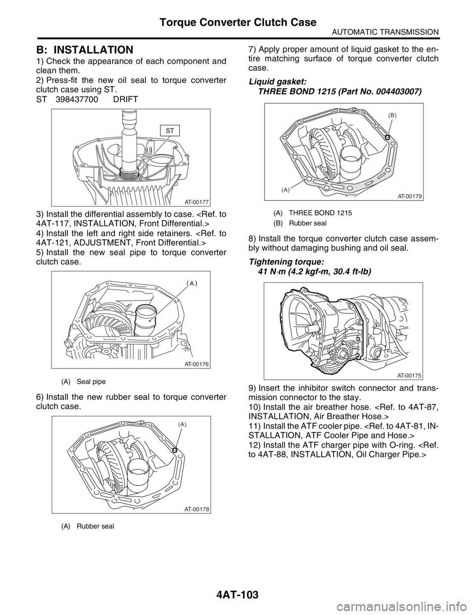
2) Press-fit the new oil seal to torque converter
clutch case using ST.
ST 398437700 DRIFT
3) Install the differential assembly to case.
4AT-117, INSTALLATION, Front Differential.>
4) Install the left and right side retainers.
4AT-121, ADJUSTMENT, Front Differential.>
5) Install the new seal pipe to torque converter
clutch case.
6) Install the new rubber seal to torque converter
clutch case.7) Apply proper amount of liquid gasket to the en-
tire matching surface of torque converter clutch
case.
Liquid gasket:
THREE BOND 1215 (Part No. 004403007)
8) Install the torque converter clutch case assem-
bly without damaging bushing and oil seal.
Tightening torque:
41 N
⋅m (4.2 kgf-m, 30.4 ft-lb)
9) Insert the inhibitor switch connector and trans-
mission connector to the stay.
10) Install the air breather hose.
INSTALLATION, Air Breather Hose.>
11) Install the ATF cooler pipe.
STALLATION, ATF Cooler Pipe and Hose.>
12) Install the ATF charger pipe with O-ring.
to 4AT-88, INSTALLATION, Oil Charger Pipe.>
(A) Seal pipe
(A) Rubber seal
AT-00177
AT-00176
AT-00178
(A)
(A) THREE BOND 1215
(B) Rubber seal
(B)
(A)
AT-00179
AT-00175
Page 2428 of 2870
4AT-114
AUTOMATIC TRANSMISSION
Drive Pinion Shaft Assembly
10) Select three or less shims from following table.
E: INSPECTION
Make sure that all component parts are free of
harmful cut, gouges, and other faults.
Adjust the teeth alignment.
ADJUSTMENT, Drive Pinion Shaft Assembly.>
F: ADJUSTMENT
1) Remove the liquid gasket completely.
2) Install the oil pump housing assembly to torque
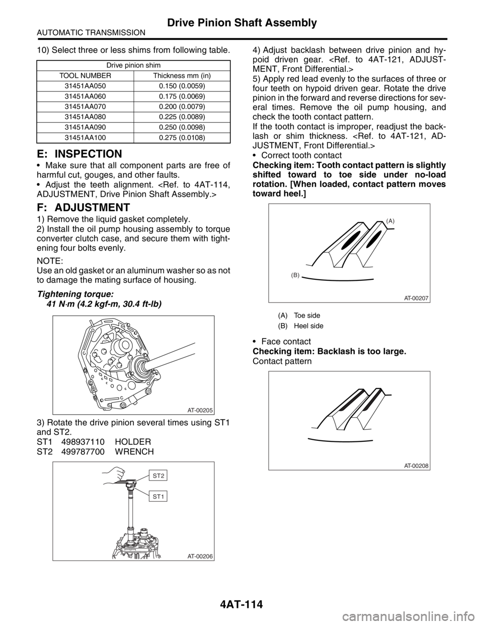
converter clutch case, and secure them with tight-
ening four bolts evenly.
NOTE:
Use an old gasket or an aluminum washer so as not
to damage the mating surface of housing.
Tightening torque:
41 N
⋅m (4.2 kgf-m, 30.4 ft-lb)
3) Rotate the drive pinion several times using ST1
and ST2.
ST1 498937110 HOLDER
ST2 499787700 WRENCH4) Adjust backlash between drive pinion and hy-
poid driven gear.
MENT, Front Differential.>
5) Apply red lead evenly to the surfaces of three or
four teeth on hypoid driven gear. Rotate the drive
pinion in the forward and reverse directions for sev-
eral times. Remove the oil pump housing, and
check the tooth contact pattern.
If the tooth contact is improper, readjust the back-
lash or shim thickness.
JUSTMENT, Front Differential.>
Correct tooth contact
Checking item: Tooth contact pattern is slightly
shifted toward to toe side under no-load
rotation. [When loaded, contact pattern moves
toward heel.]
Face contact
Checking item: Backlash is too large.
Contact pattern
Drive pinion shim
TOOL NUMBER Thickness mm (in)
31451AA050 0.150 (0.0059)
31451AA060 0.175 (0.0069)
31451AA070 0.200 (0.0079)
31451AA080 0.225 (0.0089)
31451AA090 0.250 (0.0098)
31451AA100 0.275 (0.0108)
AT-00205
AT-00206
ST2
ST1
(A) Toe side
(B) Heel side
AT-00207
(A)
(B)
AT-00208
Page 2430 of 2870
4AT-116
AUTOMATIC TRANSMISSION
Drive Pinion Shaft Assembly
6) If tooth contact is correct, mark the differential
side retainer position and loosen it. After fitting a
new O-ring and oil seal, screw in the differential
side retainer to the marked position. Tighten the
lock plate with specified torque.
Tightening torque:
25 N
⋅m (2.5 kgf-m, 18.1 ft-lb)
(A) Lock plate
AT-00214
(A)
Page 2431 of 2870
4AT-117
AUTOMATIC TRANSMISSION
Front Differential
37.Front Differential
A: REMOVAL
1) Remove the transmission assembly from vehi-
cle.
mission Assembly.>
2) Pull out the torque converter clutch assembly.
Clutch Assembly.>
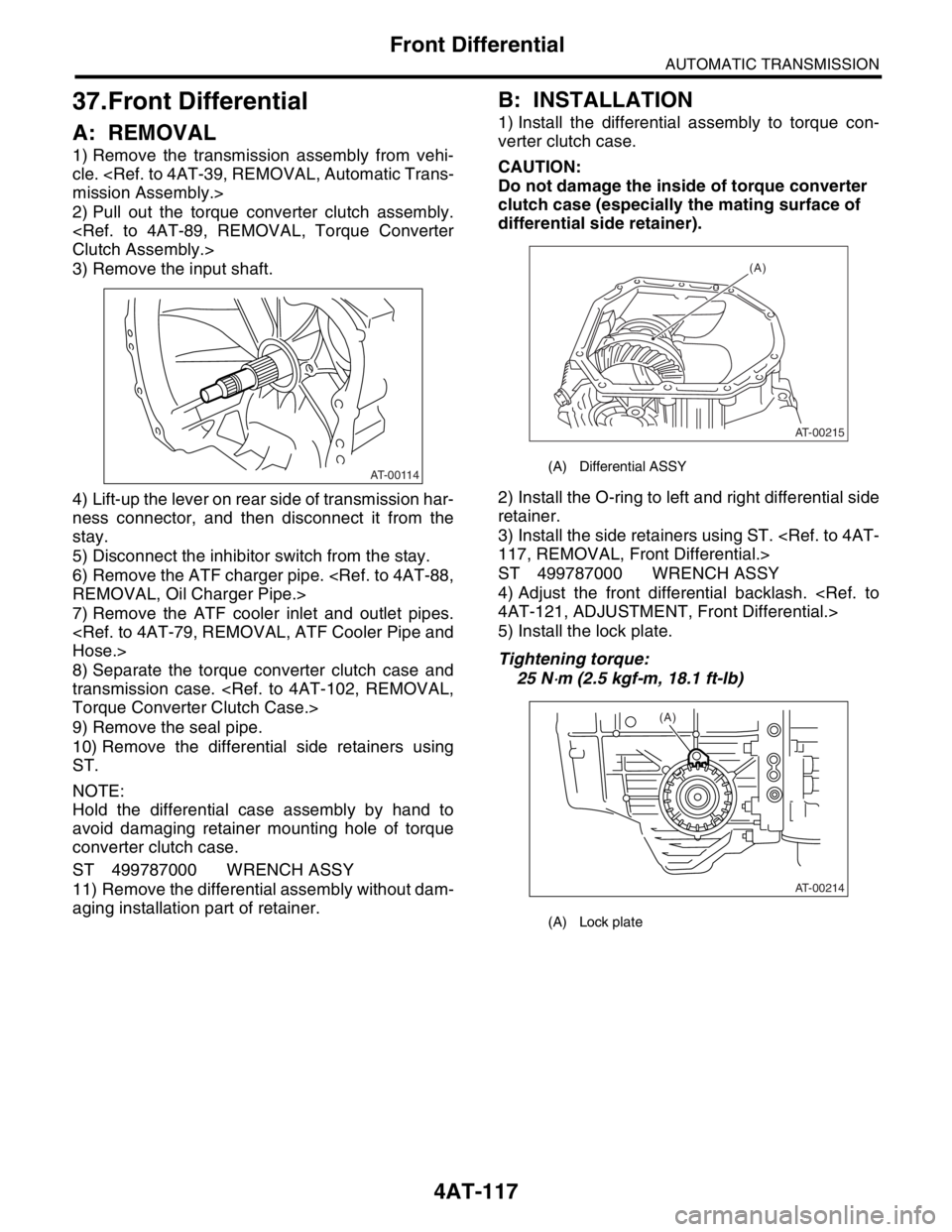
3) Remove the input shaft.
4) Lift-up the lever on rear side of transmission har-
ness connector, and then disconnect it from the
stay.
5) Disconnect the inhibitor switch from the stay.
6) Remove the ATF charger pipe.
REMOVAL, Oil Charger Pipe.>
7) Remove the ATF cooler inlet and outlet pipes.
Hose.>
8) Separate the torque converter clutch case and
transmission case.
Torque Converter Clutch Case.>
9) Remove the seal pipe.
10) Remove the differential side retainers using
ST.
NOTE:
Hold the differential case assembly by hand to
avoid damaging retainer mounting hole of torque
converter clutch case.
ST 499787000 WRENCH ASSY
11) Remove the differential assembly without dam-
aging installation part of retainer.
B: INSTALLATION
1) Install the differential assembly to torque con-
verter clutch case.
CAUTION:
Do not damage the inside of torque converter
clutch case (especially the mating surface of
differential side retainer).
2) Install the O-ring to left and right differential side
retainer.
3) Install the side retainers using ST.
117, REMOVAL, Front Differential.>
ST 499787000 WRENCH ASSY
4) Adjust the front differential backlash.
4AT-121, ADJUSTMENT, Front Differential.>
5) Install the lock plate.
Tightening torque:
25 N
⋅m (2.5 kgf-m, 18.1 ft-lb)
AT-00114(A) Differential ASSY
(A) Lock plate
AT-00215
(A)
AT-00214
(A)