Page 372 of 2870

BS-6
BODY STRUCTURE
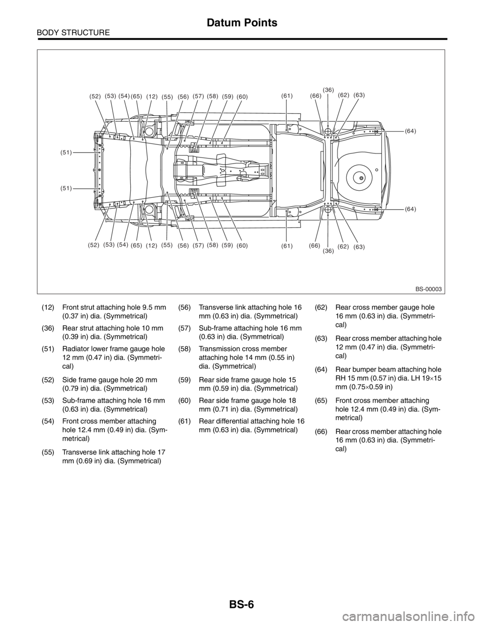
Datum Points
(12) Front strut attaching hole 9.5 mm
(0.37 in) dia. (Symmetrical)(56) Transverse link attaching hole 16
mm (0.63 in) dia. (Symmetrical)(62) Rear cross member gauge hole
16 mm (0.63 in) dia. (Symmetri-
cal)
(36) Rear strut attaching hole 10 mm
(0.39 in) dia. (Symmetrical)(57) Sub-frame attaching hole 16 mm
(0.63 in) dia. (Symmetrical)
(63) Rear cross member attaching hole
12 mm (0.47 in) dia. (Symmetri-
cal) (51) Radiator lower frame gauge hole
12 mm (0.47 in) dia. (Symmetri-
cal)(58) Transmission cross member
attaching hole 14 mm (0.55 in)
dia. (Symmetrical)
(64) Rear bumper beam attaching hole
RH 15 mm (0.57 in) dia. LH 19×15
mm (0.75×0.59 in) (52) Side frame gauge hole 20 mm
(0.79 in) dia. (Symmetrical)(59) Rear side frame gauge hole 15
mm (0.59 in) dia. (Symmetrical)
(53) Sub-frame attaching hole 16 mm
(0.63 in) dia. (Symmetrical)(60) Rear side frame gauge hole 18
mm (0.71 in) dia. (Symmetrical)(65) Front cross member attaching
hole 12.4 mm (0.49 in) dia. (Sym-
metrical)
(54) Front cross member attaching
hole 12.4 mm (0.49 in) dia. (Sym-
metrical)(61) Rear differential attaching hole 16
mm (0.63 in) dia. (Symmetrical)
(66) Rear cross member attaching hole
16 mm (0.63 in) dia. (Symmetri-
cal)
(55) Transverse link attaching hole 17
mm (0.69 in) dia. (Symmetrical)
BS-00003
(52)(53)(54)(65)(12)(55)(61)
(61)
(64)
(64)
(51)
(51)
(36)
(36)(66)
(66)(56)(57)(58)(59)(60)
(52)(53) (54)
(65)
(12)(55)
(56)(57)(58)
(59)
(60)(62)
(62)(63)
(63)
Page 386 of 2870

IDI-2
INSTRUMENTATION/DRIVER INFO
General Description
1. General Description
A: SPECIFICATION
B: CAUTION
Be careful not to damage meters and instrument panel.
Be careful not to damage meter glasses.
Make sure that electrical connector is connected securely.
After installation, make sure that each meter operates normally.
Use gloves to avoid damage and getting fingerprints on the glass surface and meter surfaces.
Do not apply excessive force to the printed circuit.
Do not drop or otherwise apply impact.
C: PREPARATION TOOL
1. GENERAL TOOL
Combination meterSpeedometer Electric pulse type
Temperature gauge Cross coil type
Fuel gauge Cross coil type
Tachometer Electric pulse type
Turn signal indicator light 14 V — 2 W
Charge indicator light 14 V — 1.4 W
Oil pressure indicator light LED
ABS warning light 14 V — 1.4 W
Malfunction indicator light LED
HI-beam indicator light 14 V — 2 W
Door open warning light LED
Seat belt warning light LED
Brake fluid and parking brake warning
light14 V — 2 W
FWD indicator light LED
AIRBAG warning light LED
Meter illumination light 14 V — 3.4 W, 14 V — 2 W
AT OIL TEMP. warning light LED
LO indicator light LED
HOLD indicator light LED
Immobilizer indicator light LED
Rear differential oil temperature warn-
ing light14 V — 2 W
Cruise indicator light 14 V — 1.4 W
Rear fog light indicator light 14 V — 2 W
POWER indicator light 14 V — 1.4 W
Low fuel warning light LED
AT select lever position indicator light 14 V — 100 mA
LCD back light 14 V — 1.4 W
TOOL NAME REMARKS
Circuit tester Used for measuring resistance and voltage.
Page 396 of 2870
IDI-12
INSTRUMENTATION/DRIVER INFO
Combination Meter Assembly
1. BULB REPLACEMENT
D: ASSEMBLY
Assemble in the reverse order of disassembly.
(1) Charge warning
(2) Tachometer
(3) Speedometer and tachometer
(4) Rear fog light indicator light
(5) HI-beam indicator
(6) Turn signal indicator RH
(7) Speedometer
(8) Turn signal indicator LH
(9) Cruise indicator light or rear differential oil tem-
perature warning light
(10) Brake warning
(11) ABS warning
(12) AT power mode indicator light
(13) Fuel gauge
(14) Temperature gauge
(15) LCD (Outside temperature indicator, Odometer
and tripmeter)
IDI00024(1) (2)(3)(5)
(6)
(7)(8)
(9)
(10)
(11)
(13)
(14)
(15)
(4)
(12)
Page 665 of 2870

FUJI HEAVY INDUSTRIES LTD. G8080GE6
2004 FORESTER SERVICE MANUAL QUICK REFERENCE INDEX
CHASSIS SECTION
This service manual has been prepared
to provide SUBARU service personnel
with the necessary information and data
for the correct maintenance and repair
of SUBARU vehicles.
This manual includes the procedures
for maintenance, disassembling, reas-
sembling, inspection and adjustment of
components and diagnostics for guid-
ance of experienced mechanics.
Please peruse and utilize this manual
fully to ensure complete repair work for
satisfying our customers by keeping
their vehicle in optimum condition.
When replacement of parts during
repair work is needed, be sure to use
SUBARU genuine parts.
All information, illustration and specifi-
cations contained in this manual are
based on the latest product information
available at the time of publication
approval.FRONT SUSPENSION FS
REAR SUSPENSION RS
WHEEL AND TIRE SYSTEM WT
DIFFERENTIAL DI
TRANSFER CASE TC
DRIVE SHAFT SYSTEM DS
ABS ABS
ABS (DIAGNOSTIC) ABS
BRAKE BR
PARKING BRAKE PB
POWER ASSISTED SYSTEM
(POWER STEERING)PS
Page 666 of 2870

TRANSFER CASE
TC
Page
1. General Description ....................................................................................2
2. Transfer Case and Extension (5MT) ...........................................................3
3. Transfer Clutch and Extension (4AT) ..........................................................4
4. Oil Seal........................................................................................................5
5. Transfer Drive Gear (5MT) ..........................................................................6
6. Transfer Driven Gear (5MT) ........................................................................7
7. Reduction Drive Gear (4AT without VTD) ...................................................8
8. Reduction Driven Gear (4AT without VTD) .................................................9
9. Center Differential .....................................................................................10
10. Transfer Clutch Pressure Test ..................................................................11
11. Transfer Duty Solenoid and Valve Body ...................................................12
Page 675 of 2870
TC-10
TRANSFER CASE
Center Differential
9. Center Differential
A: NOTE
For removal, installation and inspection work, refer
to “5MT” section.
tial.>
Page 715 of 2870

ID-6
IDENTIFICATION
Identification
Transmission
TY755XF3AA
Rear differential 1
VA1REK
Rear differential 2
HP
Option code
ECAJ
Digits Code Meaning Details
1 T Transmission T: Transmission
2 Y Transmission type Y: Full-time AWD MT center differential
Z: Full-time AWD AT MPT
3 and 4 75 Classification 75: MT
1A: AT
1B: AT
55 Series 3: AT
5: MT
6 X Transmission specifica-
tionsV: Full-time AWD 5-speed MT with viscous coupling center dif-
ferential single range
X: Full-time AWD 5-speed MT Dual range with viscous cou-
pling center differential
Z: Full-time AWD 4-speed AT with MPT
L: Full-time AWD 4-speed AT with MPT Turbo
7 F Mounted body F: 2.5L SOHC
R: 2.0L SOHC
N: 2.0L DOHC Turbo
H: 2.5L DOHC Turbo
8 3 Minor change 3: Initial
9 to 10 AA Detailed specifications Used when ordering parts. See the parts catalog for details.
Digits Code Meaning Details
1 V Fo r AW D V: AW D
2 A Type A: A type
3 1 Hypoid gear diameter
mm (in)1: 152 (6.0) dia.
4 R Installation position R: Rear
5 E Reduction gear ratio E: 4.111
F: 4.444
6 K Specification differ-
ences—
Code Reduction gear ratio LSD
HP 4.111 Viscous
JP 4.111 Viscous
CF 4.444 Viscous
Digits Code Meaning Details
1 to 2 EC Destination EC: EC
K4: K4
KS: KS
EK: EK
KA: KA
3 to 4 AJ Main option of vehicle —
Page 718 of 2870
RM-3
RECOMMENDED MATERIAL
Recommended Materials
3. LUBRICANTS
Use either the lubricants in the table below or equivalent lubricants. See the table below to choose the correct
SAE viscosity.
LubricantRecommended
Alternative
API Spec. CCMC Spec. ACEA Spec.
Engine oil SL or SJ Grade “Energy conserving” G4 or G5 A1, A2 or A3 SH or SG
Manual transmission oil GL-5 — — —
Front differential oil GL-5 — — —
Rear differential oil GL-5 — — —
SAE
0W-20
NE
E
RG
G
YCONSERVIN
APISERVICESL
RM-00006
RM-00001
SAE
5W-30
NE
E
RG
G
YCONSERVIN
APISERVICESL
AMERICANPETROLEUMINSTITUTE
FOR
GASOLINE
ENGINES
CERTIFEID
RM-00002