2004 SUBARU FORESTER differential
[x] Cancel search: differentialPage 765 of 2870
PM-28
PERIODIC MAINTENANCE SERVICE
Front & Rear Differential Oil
17.Front & Rear Differential Oil
A: REPLACEMENT
1. FRONT DIFFERENTIAL (MT MODEL)
For MT model, manual transmission oil works as
differential oil to lubricate differential. Refer to
“Transmission Oil”.
2. FRONT DIFFERENTIAL (AT MODEL)
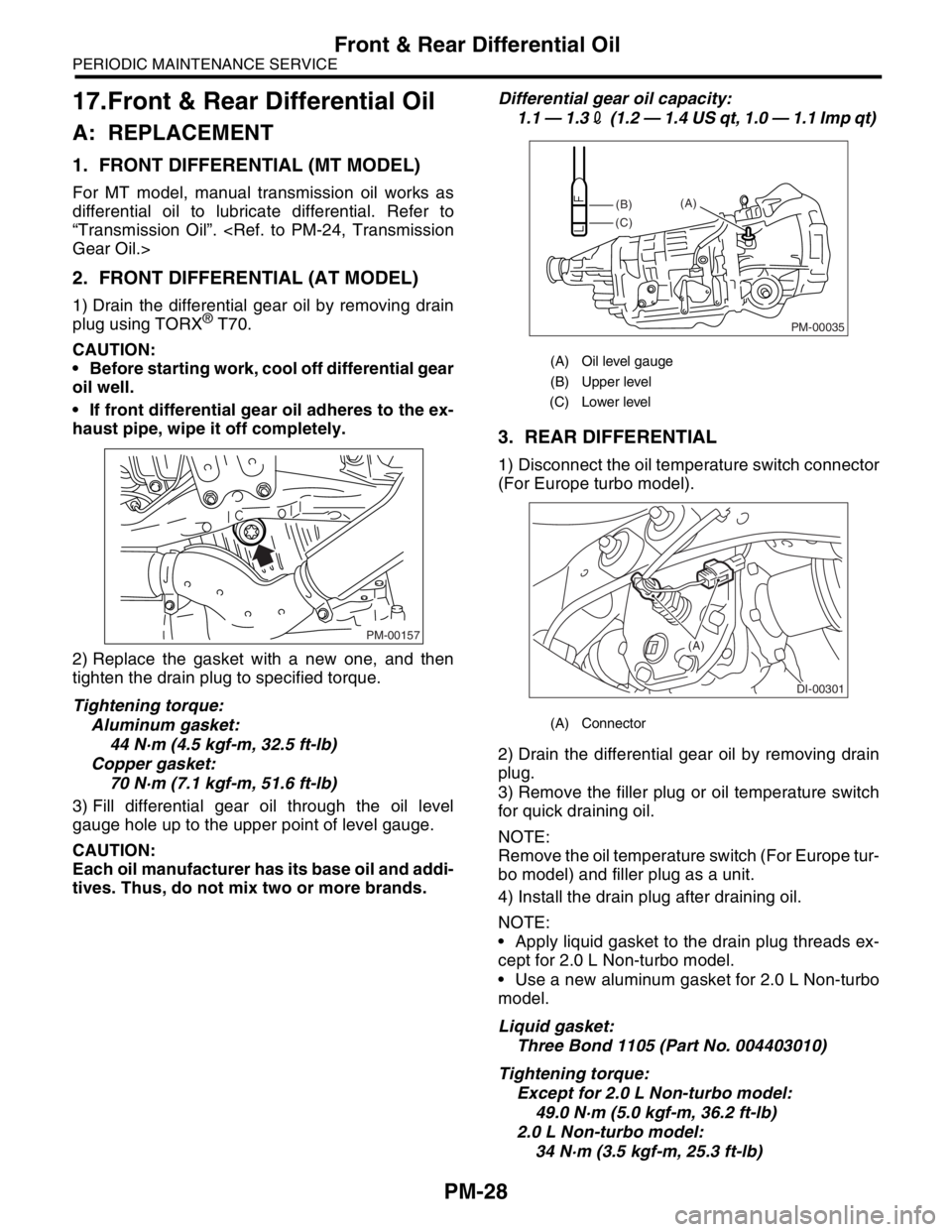
1) Drain the differential gear oil by removing drain
plug using TORX® T70.
CAUTION:
Before starting work, cool off differential gear
oil well.
If front differential gear oil adheres to the ex-
haust pipe, wipe it off completely.
2) Replace the gasket with a new one, and then
tighten the drain plug to specified torque.
Tightening torque:
Aluminum gasket:
44 N·m (4.5 kgf-m, 32.5 ft-lb)
Copper gasket:
70 N·m (7.1 kgf-m, 51.6 ft-lb)
3) Fill differential gear oil through the oil level
gauge hole up to the upper point of level gauge.
CAUTION:
Each oil manufacturer has its base oil and addi-
tives. Thus, do not mix two or more brands.Differential gear oil capacity:
1.1 — 1.32 (1.2 — 1.4 US qt, 1.0 — 1.1 Imp qt)
3. REAR DIFFERENTIAL
1) Disconnect the oil temperature switch connector
(For Europe turbo model).
2) Drain the differential gear oil by removing drain
plug.
3) Remove the filler plug or oil temperature switch
for quick draining oil.
NOTE:
Remove the oil temperature switch (For Europe tur-
bo model) and filler plug as a unit.
4) Install the drain plug after draining oil.
NOTE:
Apply liquid gasket to the drain plug threads ex-
cept for 2.0 L Non-turbo model.
Use a new aluminum gasket for 2.0 L Non-turbo
model.
Liquid gasket:
Three Bond 1105 (Part No. 004403010)
Tightening torque:
Except for 2.0 L Non-turbo model:
49.0 N·m (5.0 kgf-m, 36.2 ft-lb)
2.0 L Non-turbo model:
34 N·m (3.5 kgf-m, 25.3 ft-lb)
PM-00157
(A) Oil level gauge
(B) Upper level
(C) Lower level
(A) Connector
PM-00035
(B)
(C)(A)
DI-00301
(A)
Page 766 of 2870
PM-29
PERIODIC MAINTENANCE SERVICE
Front & Rear Differential Oil
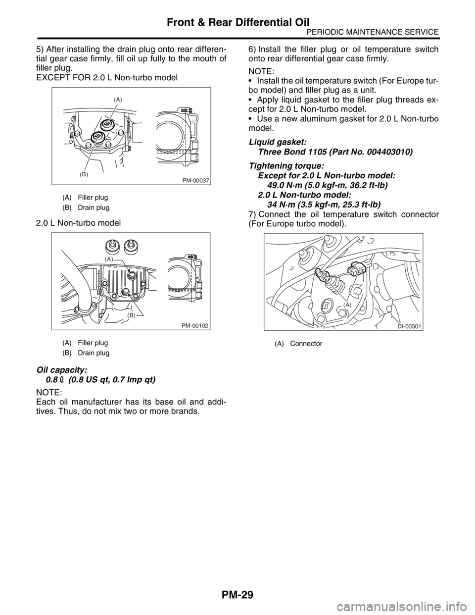
5) After installing the drain plug onto rear differen-
tial gear case firmly, fill oil up fully to the mouth of
filler plug.
EXCEPT FOR 2.0 L Non-turbo model
2.0 L Non-turbo model
Oil capacity:
0.82 (0.8 US qt, 0.7 Imp qt)
NOTE:
Each oil manufacturer has its base oil and addi-
tives. Thus, do not mix two or more brands.6) Install the filler plug or oil temperature switch
onto rear differential gear case firmly.
NOTE:
Install the oil temperature switch (For Europe tur-
bo model) and filler plug as a unit.
Apply liquid gasket to the filler plug threads ex-
cept for 2.0 L Non-turbo model.
Use a new aluminum gasket for 2.0 L Non-turbo
model.
Liquid gasket:
Three Bond 1105 (Part No. 004403010)
Tightening torque:
Except for 2.0 L Non-turbo model:
49.0 N·m (5.0 kgf-m, 36.2 ft-lb)
2.0 L Non-turbo model:
34 N·m (3.5 kgf-m, 25.3 ft-lb)
7) Connect the oil temperature switch connector
(For Europe turbo model).
(A) Filler plug
(B) Drain plug
(A) Filler plug
(B) Drain plug
PM-00037
(A)
(B)
PM-00102
(A)
(B)
(A) Connector
DI-00301
(A)
Page 1101 of 2870

EN(H4SO)-3
ENGINE (DIAGNOSTIC)
Basic Diagnostics Procedure
2. AUTOMATIC TRANSMISSION
When the DTC about automatic transmission is
shown on display, carry out the following basic
check. After that, carry out the replacement or re-
pair work.
1) ATF level check
2) Differential gear oil level check
3) ATF leak check
4) Differential gear oil level check
5) Stall Test
6) Line Pressure Test
7) Transfer Clutch Pressure Test
8) Time Lag Test
9) Road Test
10) Shift characteristics
Page 1633 of 2870

EN(H4DOTC)-3
ENGINE (DIAGNOSTIC)
Basic Diagnostics Procedure
2. AUTOMATIC TRANSMISSION
When the DTC about automatic transmission is
shown on display, carry out the following basic
check.After that, carry out the replacement or re-
pair work.
1) ATF level check
2) Differential gear oil level check
3) ATF leak check
4) Differential gear oil leak check
5) Stall Test
6) Line Pressure Test
7) Transfer Clutch Pressure Test
8) Time Lag Test
9) Road Test
10) Shift characteristics
Page 2285 of 2870
FUJI HEAVY INDUSTRIES LTD. G8080GE5
2004 FORESTER SERVICE MANUAL QUICK REFERENCE INDEX
TRANSMISSION SECTION
This service manual has been prepared
to provide SUBARU service personnel
with the necessary information and data
for the correct maintenance and repair
of SUBARU vehicles.
This manual includes the procedures
for maintenance, disassembling, reas-
sembling, inspection and adjustment of
components and diagnostics for guid-
ance of experienced mechanics.
Please peruse and utilize this manual
fully to ensure complete repair work for
satisfying our customers by keeping
their vehicle in optimum condition.
When replacement of parts during
repair work is needed, be sure to use
SUBARU genuine parts.
All information, illustration and specifi-
cations contained in this manual are
based on the latest product information
available at the time of publication
approval.CONTROL SYSTEM CS
AUTOMATIC TRANSMISSION 4AT
AUTOMATIC TRANSMISSION
(DIAGNOSTIC)4AT(H4SO)
AUTOMATIC TRANSMISSION
(DIAGNOSTIC)4AT(H4DOTC)
AUTOMATIC TRANSMISSION
(DIAGNOSTIC)4AT(H4DOTC 2.5)
MANUAL TRANSMISSION AND
DIFFERENTIAL5MT
CLUTCH SYSTEM CL
Page 2312 of 2870
FUJI HEAVY INDUSTRIES LTD. G8080GE5
2004 FORESTER SERVICE MANUAL QUICK REFERENCE INDEX
TRANSMISSION SECTION
This service manual has been prepared
to provide SUBARU service personnel
with the necessary information and data
for the correct maintenance and repair
of SUBARU vehicles.
This manual includes the procedures
for maintenance, disassembling, reas-
sembling, inspection and adjustment of
components and diagnostics for guid-
ance of experienced mechanics.
Please peruse and utilize this manual
fully to ensure complete repair work for
satisfying our customers by keeping
their vehicle in optimum condition.
When replacement of parts during
repair work is needed, be sure to use
SUBARU genuine parts.
All information, illustration and specifi-
cations contained in this manual are
based on the latest product information
available at the time of publication
approval.CONTROL SYSTEM CS
AUTOMATIC TRANSMISSION 4AT
AUTOMATIC TRANSMISSION
(DIAGNOSTIC)4AT(H4SO)
AUTOMATIC TRANSMISSION
(DIAGNOSTIC)4AT(H4DOTC)
AUTOMATIC TRANSMISSION
(DIAGNOSTIC)4AT(H4DOTC 2.5)
MANUAL TRANSMISSION AND
DIFFERENTIAL5MT
CLUTCH SYSTEM CL
Page 2313 of 2870

AUTOMATIC TRANSMISSION
4AT
Page
1. General Description ....................................................................................2
2. Automatic Transmission Fluid ...................................................................30
3. Differential Gear Oil...................................................................................31
4. Road Test..................................................................................................32
5. Stall Test ...................................................................................................33
6. Time Lag Test ...........................................................................................35
7. Line Pressure Test ....................................................................................36
8. Transfer Clutch Pressure Test ..................................................................38
9. Automatic Transmission Assembly ...........................................................39
10. Transmission Mounting System ................................................................47
11. Extension Case Oil Seal ...........................................................................49
12. Differential Side Retainer Oil Seal.............................................................50
13. Inhibitor Switch ..........................................................................................51
14. Front Vehicle Speed Sensor .....................................................................55
15. Rear Vehicle Speed Sensor ......................................................................59
16. Torque Converter Turbine Speed Sensor .................................................60
17. Control Valve Body ...................................................................................61
18. Air Bleeding of Control Valve ....................................................................70
19.
Shift Solenoids, Duty Solenoids and ATF Temperature Sensor.........................71
20. Transfer Duty Solenoid and Valve Body ...................................................73
21. ATF Filter ..................................................................................................76
22. Transmission Control Module (TCM) ........................................................77
23. Dropping Resistor .....................................................................................78
24. ATF Cooler Pipe and Hose .......................................................................79
25. ATF Cooler (With Warmer Function).........................................................84
26. Air Breather Hose......................................................................................87
27. Oil Charger Pipe........................................................................................88
28. Torque Converter Clutch Assembly ..........................................................89
29. Extension Case .........................................................................................90
30. Transfer Clutch..........................................................................................92
31. Reduction Driven Gear..............................................................................97
32. Reduction Drive Gear................................................................................99
33. Parking Pawl ...........................................................................................101
34. Torque Converter Clutch Case ...............................................................102
35. Oil Pump Housing ...................................................................................105
36. Drive Pinion Shaft Assembly ...................................................................111
37. Front Differential......................................................................................117
38. AT Main Case .........................................................................................123
39. Transmission Control Device ..................................................................142
Page 2316 of 2870
4AT-4
AUTOMATIC TRANSMISSION
General Description
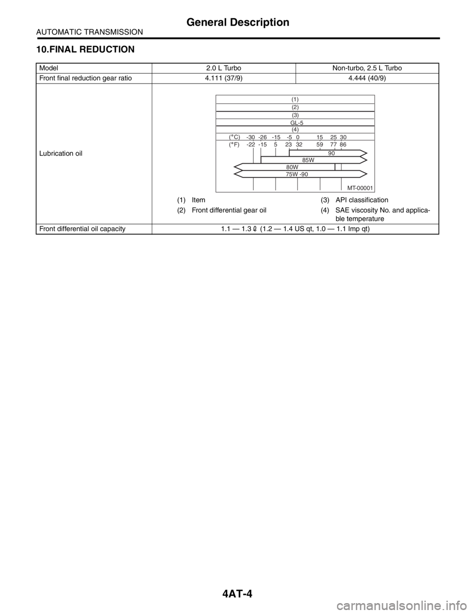
10.FINAL REDUCTION
Model 2.0 L Turbo Non-turbo, 2.5 L Turbo
Front final reduction gear ratio 4.111 (37/9) 4.444 (40/9)
Lubrication oil
(1) Item (3) API classification
(2) Front differential gear oil (4) SAE viscosity No. and applica-
ble temperature
Front differential oil capacity 1.1 — 1.32 (1.2 — 1.4 US qt, 1.0 — 1.1 Imp qt)
MT-00001
(1)
(4) GL-5(3) (2)
( C)( F)-30 -26 -15 15
90
85W
80W
75W -9025 30 -5 0-22-1523328659775