Page 2435 of 2870

4AT-121
AUTOMATIC TRANSMISSION
Front Differential
6) Using ST, install the taper roller bearing.
ST 398487700 INSTALLER
2. DIFFERENTIAL SIDE RETAINER
1) Install the bearing outer race to differential side
retainer.
2) Install a new oil seal using ST and plastic ham-
mer.
ST 18675AA000 DIFFERENTIAL OIL SEAL IN-
STALLER
3) Install a new O-ring.
E: INSPECTION
Check each component for harmful cuts, dam-
age and other faults.
Measure the backlash, and then adjust it within
specification.
tial.>
F: ADJUSTMENT
1) Using ST, screw-in the differential side retainer
until light contact is felt.
NOTE:
Screw-in the RH side slightly deeper than the LH
side.
ST 499787000 WRENCH ASSY
2) Remove the oil pump housing.
3) Remove the liquid gasket completely.
4) Install the oil pump housing assembly to torque
converter clutch case, and secure them with tight-
ening four bolts evenly.
NOTE:
Use an old gasket or an aluminum washer so as not
to damage the mating surface of housing.
Tightening torque:
41 N
⋅m (4.2 kgf-m, 30.4 ft-lb)
5) Rotate the drive pinion several times using ST1
and ST2.
ST1 498937110 HOLDER
ST2 499787700 WRENCH
(A) Taper roller bearing
AT-00225
AT-00226
ST
AT-00219
AT-00227
ST
AT-00205
AT-00206
ST2
ST1
Page 2445 of 2870

4AT-131
AUTOMATIC TRANSMISSION
AT Main Case
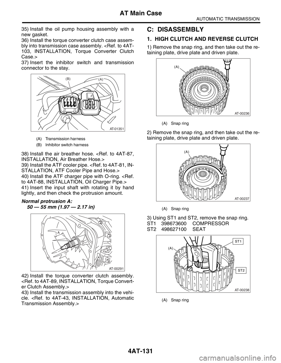
35) Install the oil pump housing assembly with a
new gasket.
36) Install the torque converter clutch case assem-
bly into transmission case assembly.
103, INSTALLATION, Torque Converter Clutch
Case.>
37) Insert the inhibitor switch and transmission
connector to the stay.
38) Install the air breather hose.
INSTALLATION, Air Breather Hose.>
39) Install the ATF cooler pipe.
STALLATION, ATF Cooler Pipe and Hose.>
40) Install the ATF charger pipe with O-ring.
to 4AT-88, INSTALLATION, Oil Charger Pipe.>
41) Insert the input shaft with rotating it by hand
lightly, and then check the protrusion amount.
Normal protrusion A:
50 — 55 mm (1.97 — 2.17 in)
42) Install the torque converter clutch assembly.
er Clutch Assembly.>
43) Install the transmission assembly into the vehi-
cle.
Transmission Assembly.>C: DISASSEMBLY
1. HIGH CLUTCH AND REVERSE CLUTCH
1) Remove the snap ring, and then take out the re-
taining plate, drive plate and driven plate.
2) Remove the snap ring, and then take out the re-
taining plate, drive plate and driven plate.
3) Using ST1 and ST2, remove the snap ring.
ST1 398673600 COMPRESSOR
ST2 498627100 SEAT
(A) Transmission harness
(B) Inhibitor switch harness
AT-01351
(B)(A)
AT-00291
A
(A) Snap ring
(A) Snap ring
(A) Snap ring
AT-00236
(A)
AT-00237
(A)
AT-00238
(A)
ST1
ST2
Page 2457 of 2870

4AT-143
AUTOMATIC TRANSMISSION
Transmission Control Device
2) Insert the range select lever, and then tighten
the bolt.
Tightening torque:
6 N
⋅m (0.6 kgf-m, 4.4 ft-lb)
3) Insert the manual plate and parking rod.
4) Insert the spring pin to manual plate.
5) Install the oil pan and control valve assembly.
Body.>
6) Turn over the transmission case to its original
position.
7) Install the pitching stopper bracket.
Tightening torque:
41 N
⋅m (4.2 kgf-m, 30.4 ft-lb)
8) Install and adjust the inhibitor switch.
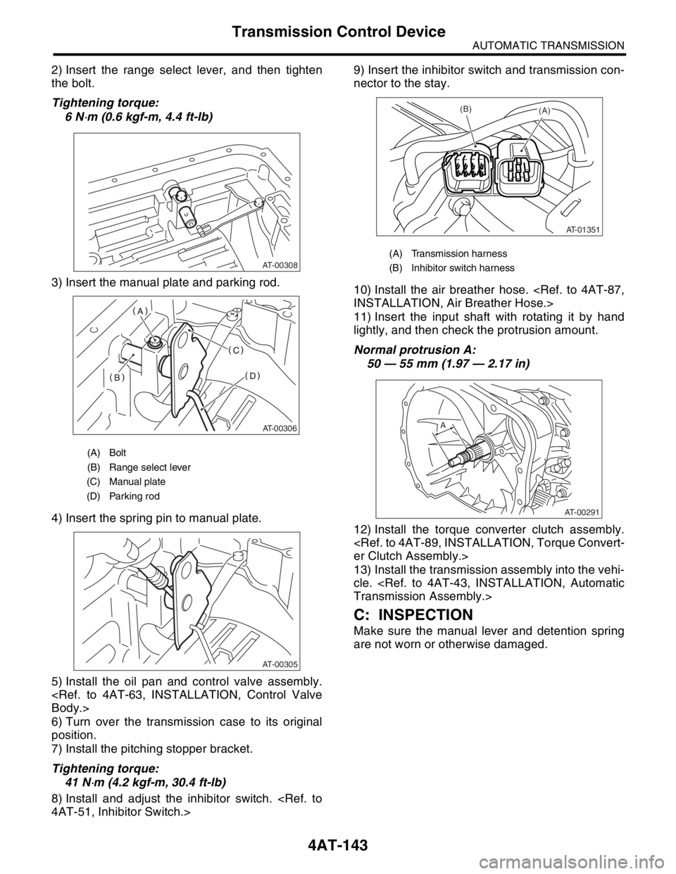
4AT-51, Inhibitor Switch.>9) Insert the inhibitor switch and transmission con-
nector to the stay.
10) Install the air breather hose.
INSTALLATION, Air Breather Hose.>
11) Insert the input shaft with rotating it by hand
lightly, and then check the protrusion amount.
Normal protrusion A:
50 — 55 mm (1.97 — 2.17 in)
12) Install the torque converter clutch assembly.
er Clutch Assembly.>
13) Install the transmission assembly into the vehi-
cle.
Transmission Assembly.>
C: INSPECTION
Make sure the manual lever and detention spring
are not worn or otherwise damaged.
(A) Bolt
(B) Range select lever
(C) Manual plate
(D) Parking rod
AT-00308
AT-00306
AT-00305
(A) Transmission harness
(B) Inhibitor switch harness
AT-01351
(B)(A)
AT-00291
A
Page 2460 of 2870

AUTOMATIC TRANSMISSION
(DIAGNOSTIC)
4AT(H4SO)
Page
1. Basic Diagnostic Procedure ........................................................................2
2. Check List for Interview ...............................................................................4
3. General Description ....................................................................................5
4. Electrical Components Location..................................................................8
5. Transmission Control Module (TCM) I/O Signal .......................................12
6. Subaru Select Monitor...............................................................................17
7. Read Diagnostic Trouble Code (DTC) ......................................................20
8. Inspection Mode ........................................................................................22
9. Clear Memory Mode..................................................................................23
10. Power Indicator Light Display....................................................................24
11. Diagnostic Procedure for Subaru Select Monitor Communication ............32
12. List of Diagnostic Trouble Code (DTC) .....................................................35
13. Diagnostic Procedure with Diagnostic Trouble Code (DTC) .....................36
14. Diagnostic Procedure without Diagnostic Trouble Code (DTC) ................84
15. Symptom Related Diagnostic ..................................................................110
Page 2461 of 2870

4AT(H4SO)-2
AUTOMATIC TRANSMISSION (DIAGNOSTIC)
Basic Diagnostic Procedure
1. Basic Diagnostic Procedure
A: PROCEDURE
Step Check Yes No
1 CHECK PRE-INSPECTION.
1) Ask the customer when and how trouble
occurred using interview checklist.
4AT(H4SO)-4, Check List for Interview.>
2) Before performing the diagnosis, inspect
following items which might influence the AT
problems.
General inspection
INSPECTION, General Description.>
Disconnection of harness connector
Visually check the damage of harness
Oil leak
Stall speed test
Line pressure test
Pressure Test.>
Transfer clutch pressure test
38, Transfer Clutch Pressure Test.>
Time lag test
Te s t . >
Road test
Inhibitor switch
Switch.>Is the unit that might influence
AT problem normal?Go to step 2.Repair or replace
each item.
2 CHECK POWER INDICATOR LIGHT.
Turn the ignition switch to ON.Does the POWER indicator
light illuminate?Go to step 4.Go to step 3.
3 CHECK POWER INDICATOR LIGHT.
1) Turn the ignition switch to OFF.
2) Repair the POWER indicator light circuit or
power supply and ground line circuit.
Indicator Light Display.>
3) Turn the ignition switch to ON.Is the POWER indicator light
illuminate?Go to step 4.Go to step 5.
4 CHECK INDICATION OF DTC.
Calling up the DTC.
Without Subaru Select Monitor
SELECT MONITOR, OPERATION, Read
Diagnostic Trouble Code (DTC).>
With Subaru Select Monitor
SELECT MONITOR, OPERATION, Read
Diagnostic Trouble Code (DTC).>
NOTE:
If the communication function of select monitor
cannot be executed normally, check the communi-
cation circuit.
NICATION FOR INITIALIZING IMPOSSIBLE,
Diagnostic Procedure for Subaru Select Monitor
Communication.>Is the DTC displayed? Go to step 6.
NOTE:
Record all DTC.Go to step 5.
Page 2463 of 2870

4AT(H4SO)-4
AUTOMATIC TRANSMISSION (DIAGNOSTIC)
Check List for Interview
2. Check List for Interview
A: CHECK
Check the following items when problem has occurred.
NOTE:
Use copies of this page for interviewing customers.
Customer’s name
Date of purchase
Date of repair
Trans. model TRANSMISSION VIN
Odometer readingkm/h (miles)
Frequency❏ Continuous ❏ Intermittent ( times a day)
Weather❏ Fine ❏ Cloudy ❏ Rainy ❏ Snowy
❏ Others
()
Place❏ High ❏ Suburbs ❏ Inner city ❏ Uphill ❏ Rough road
❏ Others
()
Outdoor temperature❏ Hot ❏ Wa r m ❏ Cool ❏ Cold
Vehicle speedkm/h (MPH)
AT warning light (POWER indicator
light)❏ Continuously lit❏ Not lit
Select lever position❏ P ❏ R ❏ N ❏ D ❏ 3 ❏ 2 ❏ 1
Driving condition❏ Not affected
❏ At racing
❏ While decelerating❏ At starting
❏ While accelerating
❏ While turning (❏ RH/❏
LH)❏ While idling
❏ While cruising
POWER switch❏ ON ❏ OFF
HOLD switch❏ ON ❏ OFF
Symptoms❏ No up-shift
❏ No down-shift
❏ No kick down
❏ Vehicle does not move (❏ Any position ❏ Particular position)
❏ Lock-up malfunction
❏ Noise or vibration
❏ Shift shock or slip
❏ Select lever does not move
❏ Others
()
Page 2465 of 2870
4AT(H4SO)-6
AUTOMATIC TRANSMISSION (DIAGNOSTIC)
General Description
5. OPERATION OF SHIFT SELECT LEVER
Make sure there is no abnormal noise, dragging or
contact pattern in each select lever range.
WARNING:
Stop the engine while checking operation of se-
lect lever.
6. POWER SWITCH
Make sure that the POWER indicator light in com-
bination meter comes ON, when turning the POW-
ER switch to ON.
7. HOLD SWITCH
Make sure that the HOLD indicator light in combi-
nation meter comes ON, when turning the HOLD
switch to ON.
AT-00413
P
R
N
D
3
2
1
AT-00319
AT-00320
Page 2467 of 2870
4AT(H4SO)-8
AUTOMATIC TRANSMISSION (DIAGNOSTIC)
Electrical Components Location
4. Electrical Components Location
A: LOCATION
1. CONTROL MODULE
LHD MODEL
RHD MODEL
(1) Engine control module (ECM) (3) Transmission control module
(TCM)(4) Data link connector
(2) AT warning light (POWER indica-
tor light)
AT-00414
(1) (2)
(3) (4)
AT-00369 (2)
(4)
(1)
(3)