Page 2354 of 2870
4AT-42
AUTOMATIC TRANSMISSION
Automatic Transmission Assembly
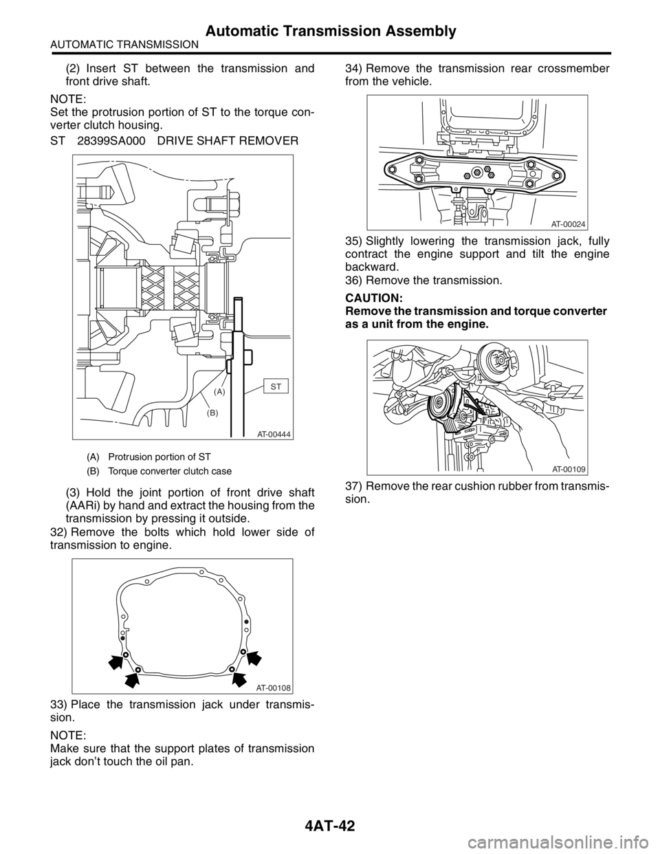
(2) Insert ST between the transmission and
front drive shaft.
NOTE:
Set the protrusion portion of ST to the torque con-
verter clutch housing.
ST 28399SA000 DRIVE SHAFT REMOVER
(3) Hold the joint portion of front drive shaft
(AARi) by hand and extract the housing from the
transmission by pressing it outside.
32) Remove the bolts which hold lower side of
transmission to engine.
33) Place the transmission jack under transmis-
sion.
NOTE:
Make sure that the support plates of transmission
jack don’t touch the oil pan.34) Remove the transmission rear crossmember
from the vehicle.
35) Slightly lowering the transmission jack, fully
contract the engine support and tilt the engine
backward.
36) Remove the transmission.
CAUTION:
Remove the transmission and torque converter
as a unit from the engine.
37) Remove the rear cushion rubber from transmis-
sion.
(A) Protrusion portion of ST
(B) Torque converter clutch case
AT-00444
ST
(A)
(B)
AT-00108
AT-00024
AT-00109
Page 2355 of 2870
4AT-43
AUTOMATIC TRANSMISSION
Automatic Transmission Assembly
B: INSTALLATION
1) Replace the differential side oil seal with a new
one.
tial Side Retainer Oil Seal.>
2) Install the rear cushion rubber to the transmis-
sion.
Tightening torque:
39 N
⋅m (4.0 kgf-m, 29 ft-lb)
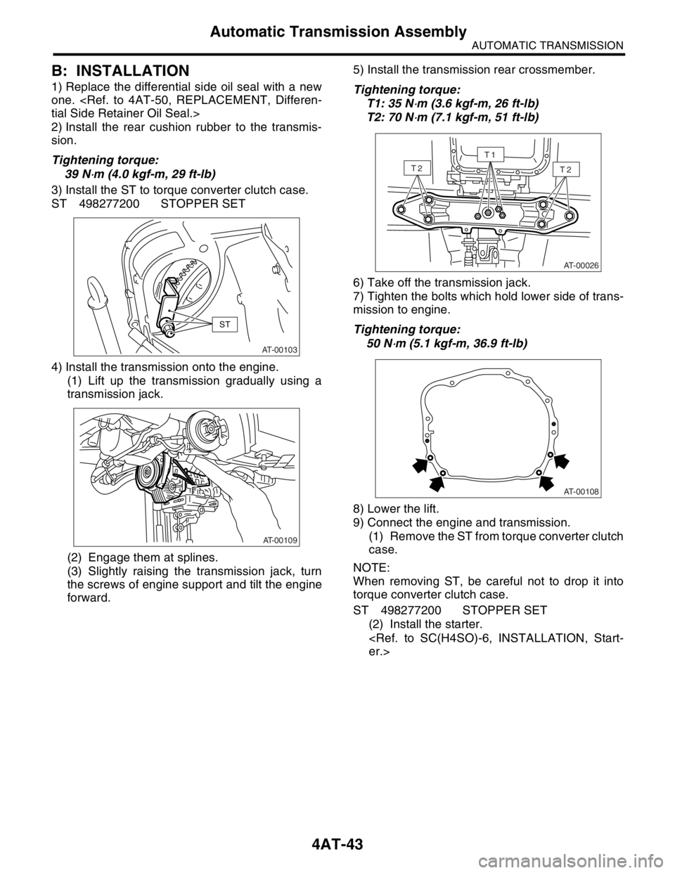
3) Install the ST to torque converter clutch case.
ST 498277200 STOPPER SET
4) Install the transmission onto the engine.
(1) Lift up the transmission gradually using a
transmission jack.
(2) Engage them at splines.
(3) Slightly raising the transmission jack, turn
the screws of engine support and tilt the engine
forward.5) Install the transmission rear crossmember.
Tightening torque:
T1: 35 N
⋅m (3.6 kgf-m, 26 ft-lb)
T2: 70 N
⋅m (7.1 kgf-m, 51 ft-lb)
6) Take off the transmission jack.
7) Tighten the bolts which hold lower side of trans-
mission to engine.
Tightening torque:
50 N
⋅m (5.1 kgf-m, 36.9 ft-lb)
8) Lower the lift.
9) Connect the engine and transmission.
(1) Remove the ST from torque converter clutch
case.
NOTE:
When removing ST, be careful not to drop it into
torque converter clutch case.
ST 498277200 STOPPER SET
(2) Install the starter.
er.>AT-00103
ST
AT-00109
AT-00026
T2T2
T1
AT-00108
Page 2356 of 2870
4AT-44
AUTOMATIC TRANSMISSION
Automatic Transmission Assembly
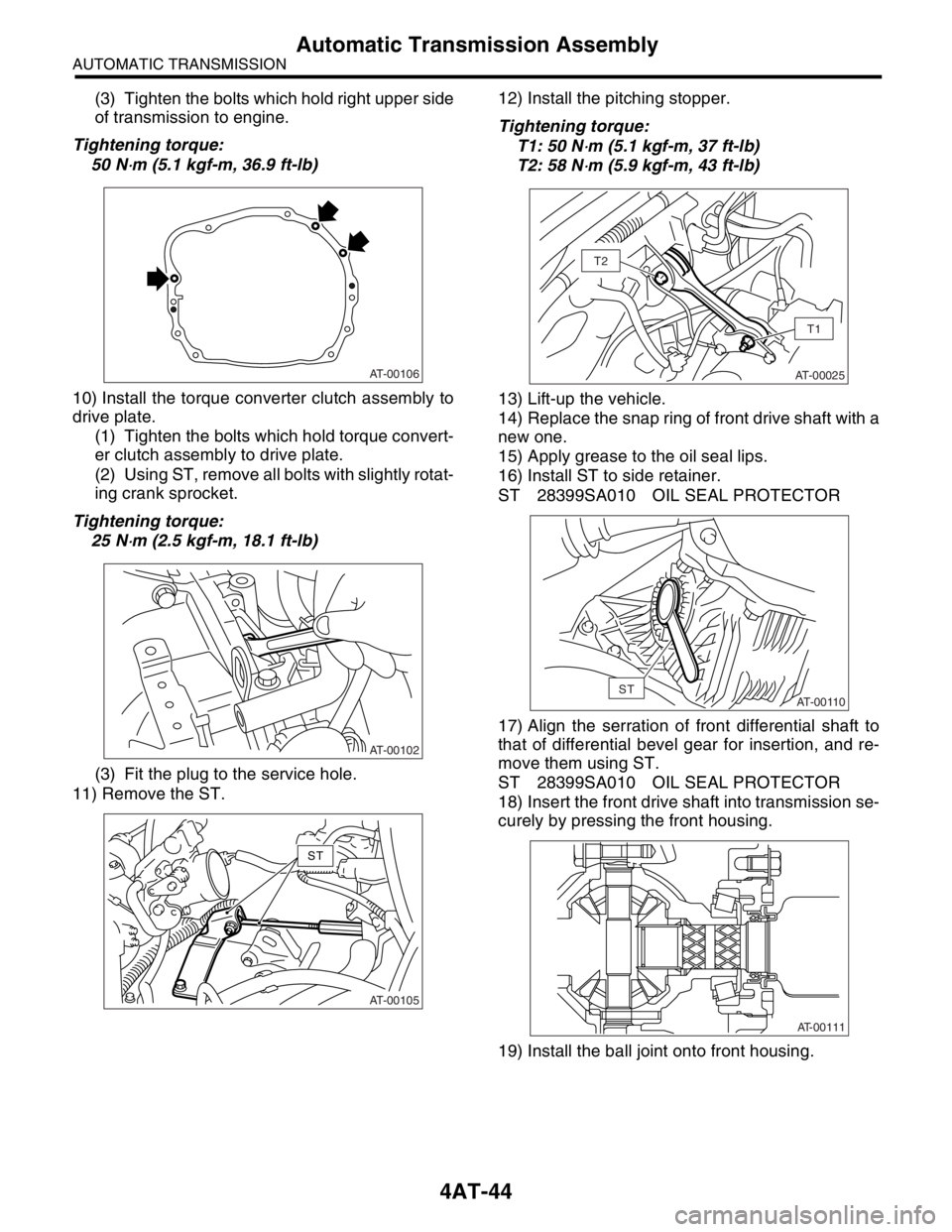
(3) Tighten the bolts which hold right upper side
of transmission to engine.
Tightening torque:
50 N
⋅m (5.1 kgf-m, 36.9 ft-lb)
10) Install the torque converter clutch assembly to
drive plate.
(1) Tighten the bolts which hold torque convert-
er clutch assembly to drive plate.
(2) Using ST, remove all bolts with slightly rotat-
ing crank sprocket.
Tightening torque:
25 N
⋅m (2.5 kgf-m, 18.1 ft-lb)
(3) Fit the plug to the service hole.
11) Remove the ST.12) Install the pitching stopper.
Tightening torque:
T1: 50 N
⋅m (5.1 kgf-m, 37 ft-lb)
T2: 58 N
⋅m (5.9 kgf-m, 43 ft-lb)
13) Lift-up the vehicle.
14) Replace the snap ring of front drive shaft with a
new one.
15) Apply grease to the oil seal lips.
16) Install ST to side retainer.
ST 28399SA010 OIL SEAL PROTECTOR
17) Align the serration of front differential shaft to
that of differential bevel gear for insertion, and re-
move them using ST.
ST 28399SA010 OIL SEAL PROTECTOR
18) Insert the front drive shaft into transmission se-
curely by pressing the front housing.
19) Install the ball joint onto front housing.
AT-00106
AT-00102
AT-00105
ST
AT-00025
T1
T2
AT-00110ST
AT-00111
Page 2363 of 2870
4AT-50
AUTOMATIC TRANSMISSION
Differential Side Retainer Oil Seal
12.Differential Side Retainer Oil
Seal
A: INSPECTION
Check the leakage of gear oil from differential side
retainer oil seal part.
If there is oil leakage, replace the oil seal.
B: REPLACEMENT
1) Lift-up the vehicle.
2) Remove the front exhaust pipe and center ex-
haust pipe.
(Non-turbo model)
Pipe.>
(Turbo model)
haust Pipe.>
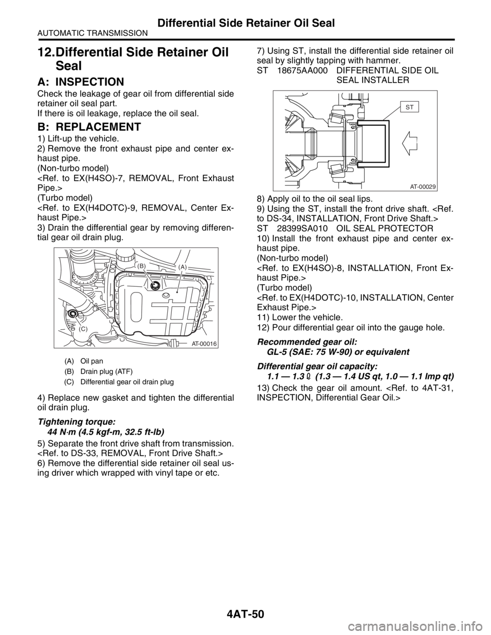
3) Drain the differential gear by removing differen-
tial gear oil drain plug.
4) Replace new gasket and tighten the differential
oil drain plug.
Tightening torque:
44 N
⋅m (4.5 kgf-m, 32.5 ft-lb)
5) Separate the front drive shaft from transmission.
6) Remove the differential side retainer oil seal us-
ing driver which wrapped with vinyl tape or etc.7) Using ST, install the differential side retainer oil
seal by slightly tapping with hammer.
ST 18675AA000 DIFFERENTIAL SIDE OIL
SEAL INSTALLER
8) Apply oil to the oil seal lips.
9) Using the ST, install the front drive shaft.
to DS-34, INSTALLATION, Front Drive Shaft.>
ST 28399SA010 OIL SEAL PROTECTOR
10) Install the front exhaust pipe and center ex-
haust pipe.
(Non-turbo model)
haust Pipe.>
(Turbo model)
Exhaust Pipe.>
11) Lower the vehicle.
12) Pour differential gear oil into the gauge hole.
Recommended gear oil:
GL-5 (SAE: 75 W-90) or equivalent
Differential gear oil capacity:
1.1 — 1.32 (1.3 — 1.4 US qt, 1.0 — 1.1 Imp qt)
13) Check the gear oil amount.
INSPECTION, Differential Gear Oil.>
(A) Oil pan
(B) Drain plug (ATF)
(C) Differential gear oil drain plug
AT-00016
(A) (B)
(C)
AT-00029
ST
Page 2364 of 2870
4AT-51
AUTOMATIC TRANSMISSION
Inhibitor Switch
13.Inhibitor Switch
A: INSPECTION
When the driving condition or starter motor opera-
tion is erroneous, first check the shift linkage for im-
proper operation. If the shift linkage is functioning
properly, check the inhibitor switch.
1) Disconnect the inhibitor switch connector.
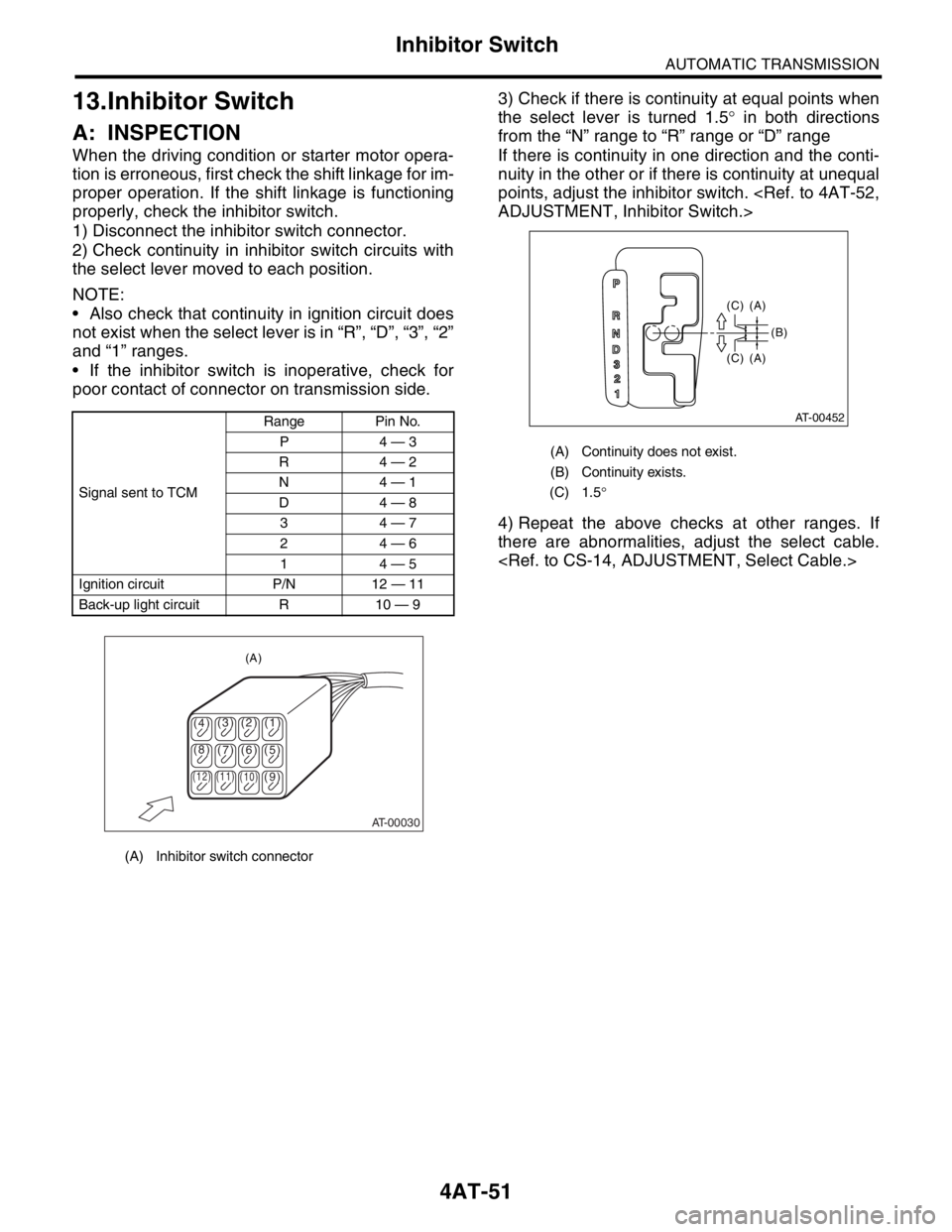
2) Check continuity in inhibitor switch circuits with
the select lever moved to each position.
NOTE:
Also check that continuity in ignition circuit does
not exist when the select lever is in “R”, “D”, “3”, “2”
and “1” ranges.
If the inhibitor switch is inoperative, check for
poor contact of connector on transmission side.3) Check if there is continuity at equal points when
the select lever is turned 1.5° in both directions
from the “N” range to “R” range or “D” range
If there is continuity in one direction and the conti-
nuity in the other or if there is continuity at unequal
points, adjust the inhibitor switch.
ADJUSTMENT, Inhibitor Switch.>
4) Repeat the above checks at other ranges. If
there are abnormalities, adjust the select cable.
Signal sent to TCMRange Pin No.
P4 — 3
R4 — 2
N4 — 1
D4 — 8
34 — 7
24 — 6
14 — 5
Ignition circuit P/N 12 — 11
Back-up light circuit R 10 — 9
(A) Inhibitor switch connector
AT-00030
(4)(3)(2) (1)
(5) (6) (7) (8)
(9)
(10) (11) (12)
(A)
(A) Continuity does not exist.
(B) Continuity exists.
(C) 1.5°
(C) (A) (C) (A)
(B)
AT-00452
P
R
N
D
3
2
1
Page 2383 of 2870

4AT-70
AUTOMATIC TRANSMISSION
Air Bleeding of Control Valve
18.Air Bleeding of Control Valve
A: PROCEDURE
1) Lift-up the vehicle with shifting the select lever to
“P” range and applying the parking brake.
2) Connect the Subaru Select Monitor to the vehi-
cle.
3) Make sure there is no trouble code using Subaru
Select Monitor.
4) Using Subaru Select Monitor, check that the
ATF temperature is in less than 60°C (140°F).
nostic Procedure.>
5) Power OFF the Subaru Select Monitor.
6) Turn the ignition switch to “OFF”.
7) Shift the select lever to “R” range.
8) Depress the brake pedal fully until the air bleed-
ing is completed.
9) Turn the ignition switch to ON.
10) Shift the select lever to “P” range, and then wait
for more than 3 seconds.
11) Shift the select lever to “R” range, and then wait
for more than 3 seconds.
12) Shift the select lever to “N” range, and then wait
for more than 3 seconds.
13) Shift the select lever to “D” range, and then wait
for more than 3 seconds.
14) Shift the select lever to “N” range, and then wait
for more than 3 seconds.
15) Slightly depress the accelerator pedal fully.
16) Slightly release the accelerator pedal fully.
17) Start the engine.
18) Shift the select lever to “D” range.
19) Turn the Subaru Select Monitor switch to ON.
20) Select {Each System Check} in «Main Menu»
of Subaru Select Monitor.
21) On the «System Selection Menu» display
screen, select the “Transmission”. Air bleeding of
control valve starts on transmission. At this time,
the POWER indicator light in combination meter
blinks at 2 Hz. When the POWER indicator light
does not blink, repeat the procedures from step 4).
22) Air bleeding of control valve is finished when
blinking of POWER indicator light in combination
meter changes from 2 Hz to 0.5 Hz.
NOTE:
When blinking of POWER indicator light changes
from 2 Hz to 4 Hz during air bleeding, repeat the
procedure from step 4).
23) Shift the select lever to “N” range, and then turn
the ignition switch to OFF.
24) Shift the select lever to the “P” range, and then
finish the air bleeding.
Page 2386 of 2870
4AT-73
AUTOMATIC TRANSMISSION
Transfer Duty Solenoid and Valve Body
20.Transfer Duty Solenoid and
Valve Body
A: REMOVAL
1) Set the vehicle on a lift.
2) Disconnect the ground cable from battery.
3) Remove the air cleaner case. (Non-turbo mod-
el).
Case.>
4) Remove the intercooler. (Turbo model)
er.>
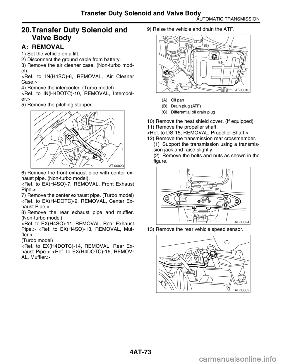
5) Remove the pitching stopper.
6) Remove the front exhaust pipe with center ex-
haust pipe. (Non-turbo model).
Pipe.>
7) Remove the center exhaust pipe. (Turbo model)
haust Pipe.>
8) Remove the rear exhaust pipe and muffler.
(Non-turbo model).
Pipe.>
fler.>
(Turbo model)
haust Pipe.>
AL, Muffler.>9) Raise the vehicle and drain the ATF.
10) Remove the heat shield cover. (If equipped)
11) Remove the propeller shaft.
12) Remove the transmission rear crossmember.
(1) Support the transmission using a transmis-
sion jack and raise slightly.
(2) Remove the bolts and nuts as shown in the
figure.
13) Remove the rear vehicle speed sensor.
AT-00023
(A) Oil pan
(B) Drain plug (ATF)
(C) Differential oil drain plug
AT-00016
(A) (B)
(C)
AT-00024
AT-00082
Page 2396 of 2870
4AT-83
AUTOMATIC TRANSMISSION
ATF Cooler Pipe and Hose
C: INSPECTION
Repair or replace any defective hoses, pipes,
clamps, and washers found from the inspection be-
low.
1) Check for ATF leaks in joints between the trans-
mission, radiator, pipes, and hoses.
2) Check for deformed clamps.
3) Lightly bend the hose and check for cracks in the
surface and other damage.
4) Pinch the hose with your fingers and check for
poor elasticity. Also check for poor elasticity in the
parts where the clamp was installed by pressing
with your fingernail.
5) Check for peeling, cracks, and deformation at
the tip of the hose.