Page 2402 of 2870
4AT-89
AUTOMATIC TRANSMISSION
Torque Converter Clutch Assembly
28.Torque Converter Clutch As-
sembly
A: REMOVAL
1) Remove the transmission assembly from vehi-
cle.
mission Assembly.>
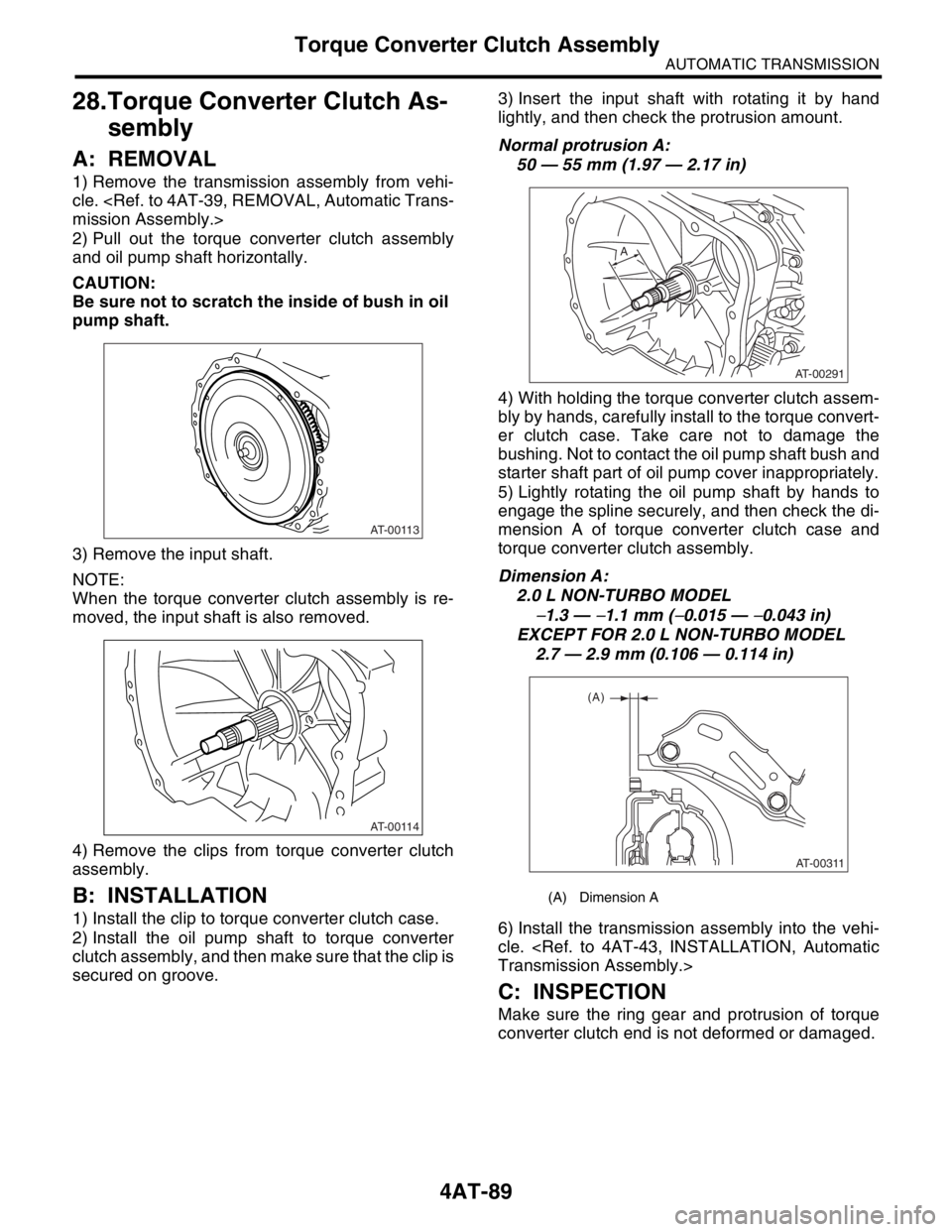
2) Pull out the torque converter clutch assembly
and oil pump shaft horizontally.
CAUTION:
Be sure not to scratch the inside of bush in oil
pump shaft.
3) Remove the input shaft.
NOTE:
When the torque converter clutch assembly is re-
moved, the input shaft is also removed.
4) Remove the clips from torque converter clutch
assembly.
B: INSTALLATION
1) Install the clip to torque converter clutch case.
2) Install the oil pump shaft to torque converter
clutch assembly, and then make sure that the clip is
secured on groove.3) Insert the input shaft with rotating it by hand
lightly, and then check the protrusion amount.
Normal protrusion A:
50 — 55 mm (1.97 — 2.17 in)
4) With holding the torque converter clutch assem-
bly by hands, carefully install to the torque convert-
er clutch case. Take care not to damage the
bushing. Not to contact the oil pump shaft bush and
starter shaft part of oil pump cover inappropriately.
5) Lightly rotating the oil pump shaft by hands to
engage the spline securely, and then check the di-
mension A of torque converter clutch case and
torque converter clutch assembly.
Dimension A:
2.0 L NON-TURBO MODEL
−1.3 — −1.1 mm (−0.015 — −0.043 in)
EXCEPT FOR 2.0 L NON-TURBO MODEL
2.7 — 2.9 mm (0.106 — 0.114 in)
6) Install the transmission assembly into the vehi-
cle.
Transmission Assembly.>
C: INSPECTION
Make sure the ring gear and protrusion of torque
converter clutch end is not deformed or damaged.
AT-00113
AT-00114
(A) Dimension A
AT-00291
A
AT-00311
(A)
Page 2404 of 2870
4AT-91
AUTOMATIC TRANSMISSION
Extension Case
Turbo model
6) Install the transmission assembly.
Transmission Assembly.>
C: DISASSEMBLY
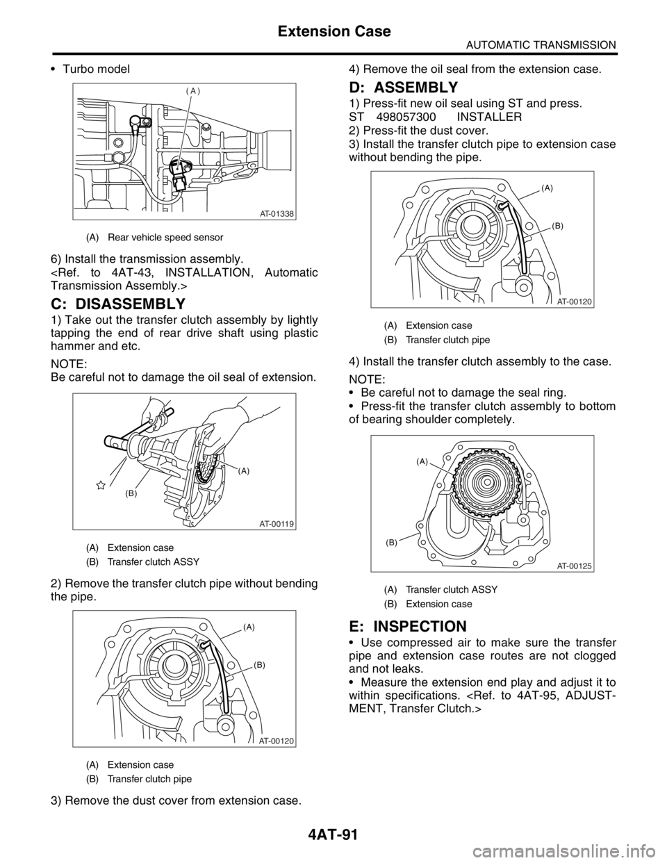
1) Take out the transfer clutch assembly by lightly
tapping the end of rear drive shaft using plastic
hammer and etc.
NOTE:
Be careful not to damage the oil seal of extension.
2) Remove the transfer clutch pipe without bending
the pipe.
3) Remove the dust cover from extension case.4) Remove the oil seal from the extension case.
D: ASSEMBLY
1) Press-fit new oil seal using ST and press.
ST 498057300 INSTALLER
2) Press-fit the dust cover.
3) Install the transfer clutch pipe to extension case
without bending the pipe.
4) Install the transfer clutch assembly to the case.
NOTE:
Be careful not to damage the seal ring.
Press-fit the transfer clutch assembly to bottom
of bearing shoulder completely.
E: INSPECTION
Use compressed air to make sure the transfer
pipe and extension case routes are not clogged
and not leaks.
Measure the extension end play and adjust it to
within specifications.
MENT, Transfer Clutch.>
(A) Rear vehicle speed sensor
(A) Extension case
(B) Transfer clutch ASSY
(A) Extension case
(B) Transfer clutch pipe
AT-01338
(A)
AT-00119
(A)
(B)
AT-00120
(A)
(B)
(A) Extension case
(B) Transfer clutch pipe
(A) Transfer clutch ASSY
(B) Extension case
AT-00120
(A)
(B)
AT-00125
(A)
(B)
Page 2416 of 2870
4AT-102
AUTOMATIC TRANSMISSION
Torque Converter Clutch Case
34.Torque Converter Clutch
Case
A: REMOVAL
1) Remove the transmission assembly from vehi-
cle.
mission Assembly.>
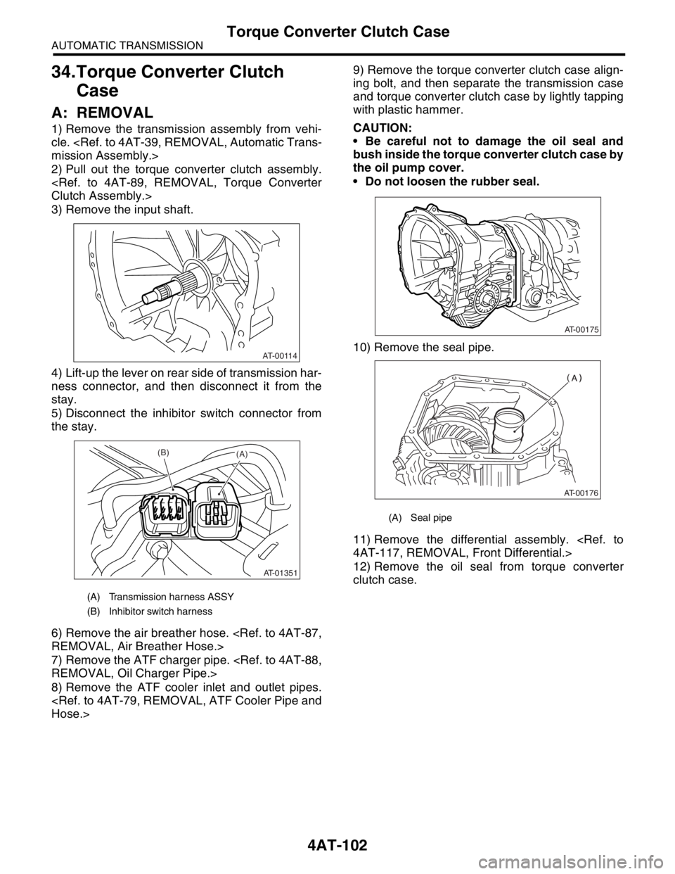
2) Pull out the torque converter clutch assembly.
Clutch Assembly.>
3) Remove the input shaft.
4) Lift-up the lever on rear side of transmission har-
ness connector, and then disconnect it from the
stay.
5) Disconnect the inhibitor switch connector from
the stay.
6) Remove the air breather hose.
REMOVAL, Air Breather Hose.>
7) Remove the ATF charger pipe.
REMOVAL, Oil Charger Pipe.>
8) Remove the ATF cooler inlet and outlet pipes.
Hose.>9) Remove the torque converter clutch case align-
ing bolt, and then separate the transmission case
and torque converter clutch case by lightly tapping
with plastic hammer.
CAUTION:
Be careful not to damage the oil seal and
bush inside the torque converter clutch case by
the oil pump cover.
Do not loosen the rubber seal.
10) Remove the seal pipe.
11) Remove the differential assembly.
4AT-117, REMOVAL, Front Differential.>
12) Remove the oil seal from torque converter
clutch case.
(A) Transmission harness ASSY
(B) Inhibitor switch harness
AT-00114
AT-01351
(B)(A)
(A) Seal pipe
AT-00175
AT-00176
Page 2418 of 2870
4AT-104
AUTOMATIC TRANSMISSION
Torque Converter Clutch Case
13) Insert the input shaft with rotating it by hand
lightly, and then check the protrusion amount.
Normal protrusion A:
50 — 55 mm (1.97 — 2.17 in)
14) Install the torque converter clutch assembly.
er Clutch Assembly.>
15) Install the transmission assembly into the vehi-
cle.
Transmission Assembly.>
C: INSPECTION
Measure the backlash, and then adjust it within
specification.
Drive Pinion Shaft Assembly.>
AT-00291
A
Page 2420 of 2870
4AT-106
AUTOMATIC TRANSMISSION
Oil Pump Housing
2) Install the torque converter clutch case to trans-
mission case.
Torque Converter Clutch Assembly.>
3) Install the reduction driven gear.
97, INSTALLATION, Reduction Driven Gear.>
4) Install the reduction drive gear.
INSTALLATION, Reduction Drive Gear.>
5) Align the transmission case and extension case.
Case.>
6) Insert the inhibitor switch and transmission con-
nector to the stay.
7) Install the ATF cooler pipe.
STALLATION, ATF Cooler Pipe and Hose.>
8) Install the ATF charger pipe with O-ring.
4AT-88, INSTALLATION, Oil Charger Pipe.>
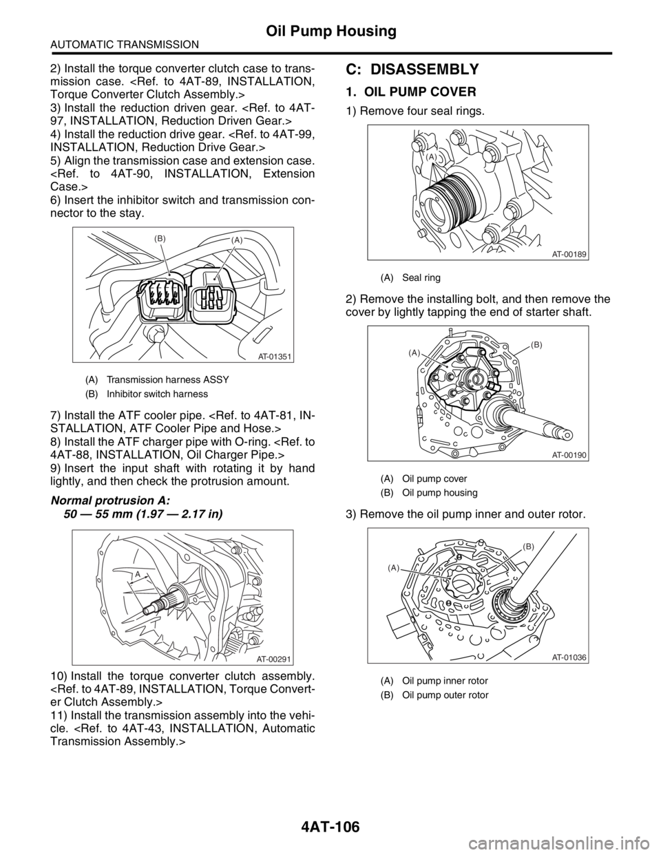
9) Insert the input shaft with rotating it by hand
lightly, and then check the protrusion amount.
Normal protrusion A:
50 — 55 mm (1.97 — 2.17 in)
10) Install the torque converter clutch assembly.
er Clutch Assembly.>
11) Install the transmission assembly into the vehi-
cle.
Transmission Assembly.>C: DISASSEMBLY
1. OIL PUMP COVER
1) Remove four seal rings.
2) Remove the installing bolt, and then remove the
cover by lightly tapping the end of starter shaft.
3) Remove the oil pump inner and outer rotor.
(A) Transmission harness ASSY
(B) Inhibitor switch harness
AT-01351
(B)(A)
AT-00291
A
(A) Seal ring
(A) Oil pump cover
(B) Oil pump housing
(A) Oil pump inner rotor
(B) Oil pump outer rotor
AT-00189
(A)
AT-00190
(A)(B)
AT-01036
(A)(B)
Page 2426 of 2870
4AT-112
AUTOMATIC TRANSMISSION
Drive Pinion Shaft Assembly
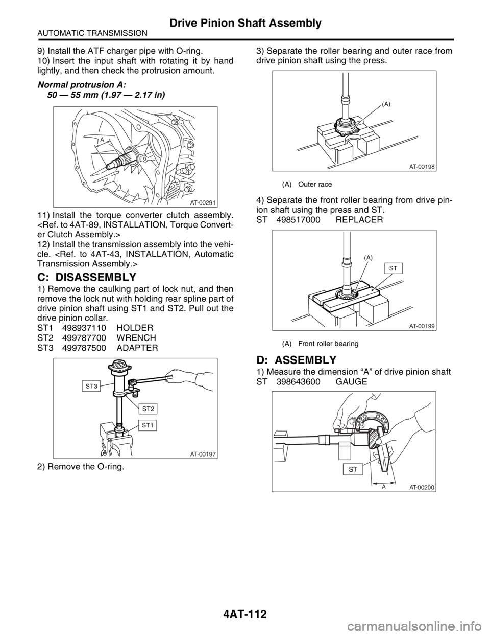
9) Install the ATF charger pipe with O-ring.
10) Insert the input shaft with rotating it by hand
lightly, and then check the protrusion amount.
Normal protrusion A:
50 — 55 mm (1.97 — 2.17 in)
11) Install the torque converter clutch assembly.
er Clutch Assembly.>
12) Install the transmission assembly into the vehi-
cle.
Transmission Assembly.>
C: DISASSEMBLY
1) Remove the caulking part of lock nut, and then
remove the lock nut with holding rear spline part of
drive pinion shaft using ST1 and ST2. Pull out the
drive pinion collar.
ST1 498937110 HOLDER
ST2 499787700 WRENCH
ST3 499787500 ADAPTER
2) Remove the O-ring.3) Separate the roller bearing and outer race from
drive pinion shaft using the press.
4) Separate the front roller bearing from drive pin-
ion shaft using the press and ST.
ST 498517000 REPLACER
D: ASSEMBLY
1) Measure the dimension “A” of drive pinion shaft
ST 398643600 GAUGE
AT-00291
A
AT-00197
ST1
ST3
ST2
(A) Outer race
(A) Front roller bearing
AT-00198
(A)
AT-00199
(A)
ST
A
AT-00200
Page 2428 of 2870
4AT-114
AUTOMATIC TRANSMISSION
Drive Pinion Shaft Assembly
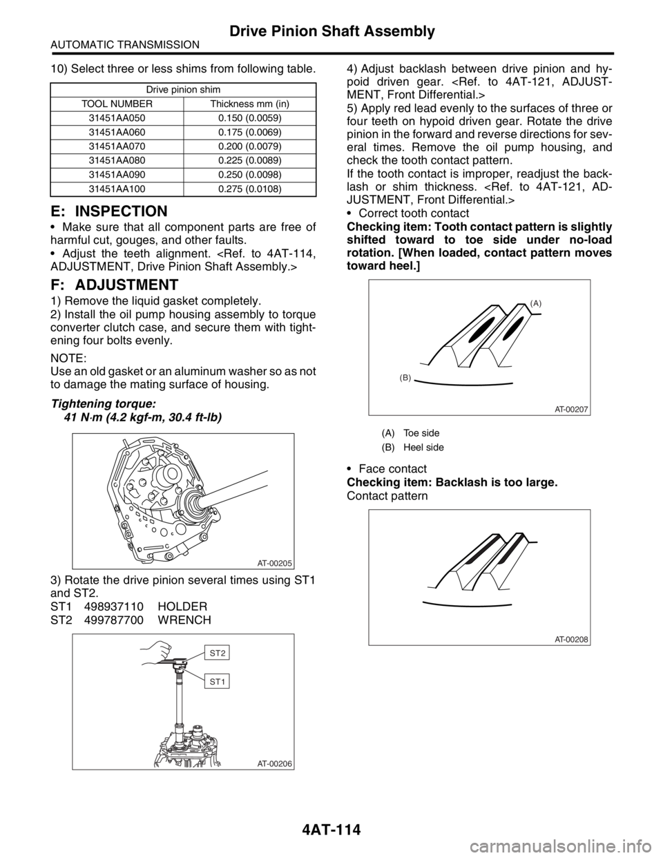
10) Select three or less shims from following table.
E: INSPECTION
Make sure that all component parts are free of
harmful cut, gouges, and other faults.
Adjust the teeth alignment.
ADJUSTMENT, Drive Pinion Shaft Assembly.>
F: ADJUSTMENT
1) Remove the liquid gasket completely.
2) Install the oil pump housing assembly to torque
converter clutch case, and secure them with tight-
ening four bolts evenly.
NOTE:
Use an old gasket or an aluminum washer so as not
to damage the mating surface of housing.
Tightening torque:
41 N
⋅m (4.2 kgf-m, 30.4 ft-lb)
3) Rotate the drive pinion several times using ST1
and ST2.
ST1 498937110 HOLDER
ST2 499787700 WRENCH4) Adjust backlash between drive pinion and hy-
poid driven gear.
MENT, Front Differential.>
5) Apply red lead evenly to the surfaces of three or
four teeth on hypoid driven gear. Rotate the drive
pinion in the forward and reverse directions for sev-
eral times. Remove the oil pump housing, and
check the tooth contact pattern.
If the tooth contact is improper, readjust the back-
lash or shim thickness.
JUSTMENT, Front Differential.>
Correct tooth contact
Checking item: Tooth contact pattern is slightly
shifted toward to toe side under no-load
rotation. [When loaded, contact pattern moves
toward heel.]
Face contact
Checking item: Backlash is too large.
Contact pattern
Drive pinion shim
TOOL NUMBER Thickness mm (in)
31451AA050 0.150 (0.0059)
31451AA060 0.175 (0.0069)
31451AA070 0.200 (0.0079)
31451AA080 0.225 (0.0089)
31451AA090 0.250 (0.0098)
31451AA100 0.275 (0.0108)
AT-00205
AT-00206
ST2
ST1
(A) Toe side
(B) Heel side
AT-00207
(A)
(B)
AT-00208
Page 2432 of 2870
4AT-118
AUTOMATIC TRANSMISSION
Front Differential
6) Install the new seal pipe to torque converter
clutch case.
7) Install the torque converter clutch case to trans-
mission case.
Torque Converter Clutch Case.>
8) Insert the inhibitor switch and transmission con-
nector to the stay.
9) Install the ATF cooler pipe.
STALLATION, ATF Cooler Pipe and Hose.>
10) Install the ATF charger pipe with O-ring.
to 4AT-88, INSTALLATION, Oil Charger Pipe.>11) Insert the input shaft with rotating it by hand
lightly, and then check the protrusion amount.
Normal protrusion A:
50 — 55 mm (1.97 — 2.17 in)
12) Install the torque converter clutch assembly.
er Clutch Assembly.>
13) Install the transmission assembly into the vehi-
cle.
Transmission Assembly.>
C: DISASSEMBLY
1. DIFFERENTIAL CASE ASSEMBLY
1) Remove taper roller bearing using ST and press.
ST 498077000 REMOVER
(A) Seal pipe
(A) Transmission harness ASSY
(B) Inhibitor switch harness
AT-00176
AT-01351
(B)(A)
AT-00291
A
AT-00216