Page 1404 of 2870

FU(H4DOTC)-49
FUEL INJECTION (FUEL SYSTEM)
Exhaust Temperature Sensor
19.Exhaust Temperature Sensor
A: REMOVAL
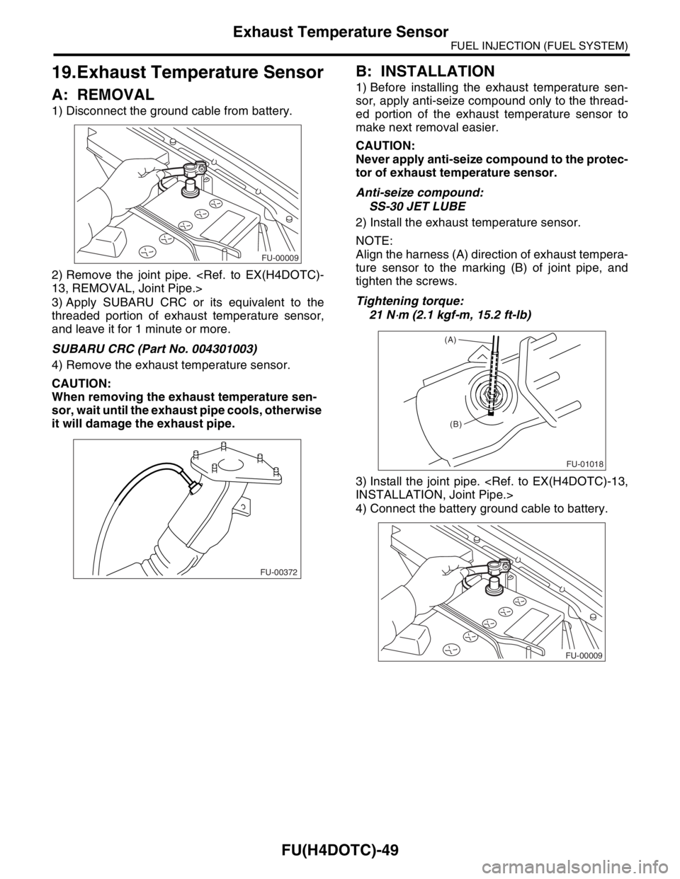
1) Disconnect the ground cable from battery.
2) Remove the joint pipe.
13, REMOVAL, Joint Pipe.>
3) Apply SUBARU CRC or its equivalent to the
threaded portion of exhaust temperature sensor,
and leave it for 1 minute or more.
SUBARU CRC (Part No. 004301003)
4) Remove the exhaust temperature sensor.
CAUTION:
When removing the exhaust temperature sen-
sor, wait until the exhaust pipe cools, otherwise
it will damage the exhaust pipe.
B: INSTALLATION
1) Before installing the exhaust temperature sen-
sor, apply anti-seize compound only to the thread-
ed portion of the exhaust temperature sensor to
make next removal easier.
CAUTION:
Never apply anti-seize compound to the protec-
tor of exhaust temperature sensor.
Anti-seize compound:
SS-30 JET LUBE
2) Install the exhaust temperature sensor.
NOTE:
Align the harness (A) direction of exhaust tempera-
ture sensor to the marking (B) of joint pipe, and
tighten the screws.
Tightening torque:
21 N
⋅m (2.1 kgf-m, 15.2 ft-lb)
3) Install the joint pipe.
INSTALLATION, Joint Pipe.>
4) Connect the battery ground cable to battery.
FU-00009
FU-00372
FU-01018
(A)
(B)
FU-00009
Page 1417 of 2870

FU(H4DOTC)-62
FUEL INJECTION (FUEL SYSTEM)
Fuel Pump
27.Fuel Pump
A: REMOVAL
WARNING:
Place “NO FIRE” signs near working area.
Be careful not to spill fuel on floor.
NOTE:
Fuel pump assembly consists of fuel pump and fuel
level sensor.
1) Release the fuel pressure.
FU(H4DOTC)-54, RELEASING OF FUEL PRES-
SURE, OPERATION, Fuel.>
2) Open the fuel filler flap lid and remove the fuel
filler cap.
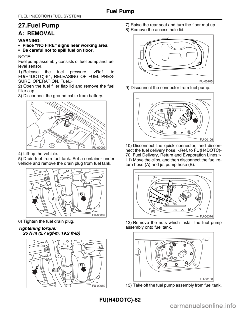
3) Disconnect the ground cable from battery.
4) Lift-up the vehicle.
5) Drain fuel from fuel tank. Set a container under
vehicle and remove the drain plug from fuel tank.
6) Tighten the fuel drain plug.
Tightening torque:
26 N
⋅m (2.7 kgf-m, 19.2 ft-lb)7) Raise the rear seat and turn the floor mat up.
8) Remove the access hole lid.
9) Disconnect the connector from fuel pump.
10) Disconnect the quick connector, and discon-
nect the fuel delivery hose.
70, Fuel Delivery, Return and Evaporation Lines.>
11) Move the clips, and then disconnect the fuel re-
turn hose (A) and jet pump hose (B).
12) Remove the nuts which install the fuel pump
assembly onto fuel tank.
13) Take off the fuel pump assembly from fuel tank.
FU-00009
FU-00089
FU-00089
FU-00105
FU-00106
FU-00376
(B)
(A)
FU-00108
Page 1419 of 2870
FU(H4DOTC)-64
FUEL INJECTION (FUEL SYSTEM)
Fuel Level Sensor
28.Fuel Level Sensor
A: REMOVAL
WARNING:
Place “NO FIRE” signs near working area.
Be careful not to spill fuel on floor.
NOTE:
Fuel level sensor is built in fuel pump assembly.
1) Remove the fuel pump assembly.
FU(H4DOTC)-62, REMOVAL, Fuel Pump.>
2) Disconnect the connector from fuel pump brack-
et.
3) Remove the bolt which installs the fuel level sen-
sor on mounting bracket.
B: INSTALLATION
Install in the reverse order of removal.
FU-00111
FU-00112
Page 1420 of 2870
FU(H4DOTC)-65
FUEL INJECTION (FUEL SYSTEM)
Fuel Sub Level Sensor
29.Fuel Sub Level Sensor
A: REMOVAL
WARNING:
Place “NO FIRE” signs near working area.
Be careful not to spill fuel on floor.
1) Disconnect the ground cable from battery.
2) Lift-up the vehicle.
3) Drain fuel from fuel tank. Set a container under
vehicle and remove the drain plug from fuel tank.
4) Tighten the fuel drain plug.
Tightening torque:
26 N
⋅m (2.7 kgf-m, 19.2 ft-lb)
5) Remove the rear seat.6) Remove the service hole cover.
7) Disconnect the connector from fuel sub level
sensor.
8) Disconnect the fuel jet pump hose.
9) Remove the bolts which install the fuel sub level
sensor on fuel tank.
10) Remove the fuel sub level sensor.
FU-00009
FU-00089
FU-00089
FU-00113
FU-00114
FU-00115
FU-00116
Page 1421 of 2870
FU(H4DOTC)-66
FUEL INJECTION (FUEL SYSTEM)
Fuel Sub Level Sensor
B: INSTALLATION
Install in the reverse order of removal.
Tightening torque:
4.4 N
⋅m (0.45 kgf-m, 3.3 ft-lb)
FU-00115
Page 1428 of 2870

FU(H4DOTC)-73
FUEL INJECTION (FUEL SYSTEM)
Fuel System Trouble in General
34.Fuel System Trouble in General
A: INSPECTION
NOTE:
When the vehicle is left unattended for an ex-
tended period of time, water may accumulate in the
fuel tank.
To prevent water condensation.
(1) Top off the fuel tank or drain the fuel com-
pletely.
(2) Drain the water condensation from the fuel
filter.
Refilling the fuel tank.
Refill the fuel tank while there is still some fuel left in
the tank.
Protecting the fuel system against freezing and
water condensation.
Cold areas
In snow-covered areas, mountainous areas, skiing
areas, etc. where ambient temperatures drop be-
low 0°C (32°F) throughout the winter season, use
an anti-freeze solution in the fuel tank. Refueling
will also complement the effect of anti-freeze solu-
tion each time the fuel level drops to about one-half. After the winter season, drain the water which
may have accumulated in the fuel filter and fuel
tank in the manner same as that described under
Affected areas below.
Affected areas
When the water condensation is notched in the fuel
filter, drain the water from both the fuel filter and
fuel tank or use a water removing agent (or anti-
freeze solution) in the fuel tank.
Observe the instructions, notes, etc., indicated
on the label affixed to the anti-freeze solution (wa-
ter removing agent) container before use.
Trouble and possible cause Corrective action
1. Insufficient fuel supply to the injector
1) Fuel pump will not operate.
❍Defective terminal contact.Inspect connections, especially ground, and tighten
securely.
❍Trouble in electromagnetic or electronic circuit parts. Replace fuel pump.
2) Lowering of fuel pump function. Replace fuel pump.
3) Clogged dust or water in the fuel filter. Replace fuel filter, clean or replace fuel tank.
4) Clogged or bent fuel pipe or hose. Clean, correct or replace fuel pipe or hose.
5) Air is mixed in the fuel system. Inspect or retighten each connection part.
6) Clogged or bent breather tube or pipe. Clean, correct or replace air breather tube or pipe.
7) Damaged diaphragm of pressure regulator. Replace.
2. Leakage or blow out fuel
1) Loosened joints of the fuel pipe. Retightening.
2) Cracked fuel pipe, hose and fuel tank. Replace.
3) Defective welding part on the fuel tank. Replace.
4) Defective drain packing of the fuel tank. Replace.
5) Clogged or bent air breather tube or air vent tube.Clean, correct or replace air breather tube or air vent
tube.
3. Gasoline smell inside of compartment
1)Loose joints at air breather tube, air vent tube and fuel filler
pipe.Retightening.
2) Defective packing air tightness on the fuel saucer. Correct or replace packing.
3) Cracked fuel separator. Replace separator.
4) Inoperative fuel pump modulator or circuit. Replace.
4. Defective fuel meter indicator
1) Defective operation of fuel level sensor. Replace.
2) Defective operation of fuel meter. Replace.
5. Noise
1) Large operation noise or vibration of fuel pump. Replace.
Page 1432 of 2870
EC(H4DOTC)-2
EMISSION CONTROL (AUX. EMISSION CONTROL DEVICE)
General Description
1. General Description
A: CAUTION
Wear working clothing, including a cap, protec-
tive goggles, and protective shoes during opera-
tion.
Remove contamination including dirt and corro-
sion before removal, installation or disassembly.
Keep the disassembled parts in order and pro-
tect them from dust or dirt.
Before removal, installation or disassembly, be
sure to clarify the failure. Avoid unnecessary re-
moval, installation, disassembly, and replacement.
Be careful not to burn your hands, because each
part on the vehicle is hot after running.
Be sure to tighten fasteners including bolts and
nuts to the specified torque.
Place shop jacks or rigid racks at the specified
points.
Before disconnecting electrical connectors of
sensors or units, be sure to disconnect the ground
cable from battery.
Page 1441 of 2870
IN(H4DOTC)-2
INTAKE (INDUCTION)
General Description
1. General Description
A: COMPONENT
1. AIR CLEANER
(1) Mass air flow and intake air tem-
perature sensor(7) Air cleaner lower case (14) Cushion
(8) Cushion rubber
(2) Air cleaner upper cover (9) Air intake ductTightening torque: N
⋅m (kgf-m, ft-lb)
(3) Air cleaner element (10) Resonator chamber ASSYT1: 7.5 (0.76, 5.5)
(4) Spacer (11) Cushion rubberT2: 33 (3.4, 24.6)
(5) Bushing (12) ClampT3: 2.5 (0.25, 1.8)
(6) Clip (13) Air intake bootT4: 1.7 (0.17, 1.2)
(3)
(12)
(12) (13)
(6)
(6)(7)
(4)
(5) (8)
(14)
(11)
(10)T3
T3
T2
(9)
T1
T1
T1
T1
T4
(2)
(1)
IN-00001