Page 1445 of 2870
IN(H4DOTC)-6
INTAKE (INDUCTION)
General Description
B: CAUTION
Wear working clothing, including a cap, protec-
tive goggles, and protective shoes during opera-
tion.
Remove contamination including dirt and corro-
sion before removal, installation or disassembly.
Keep the disassembled parts in order and pro-
tect them from dust or dirt.
Before removal, installation or disassembly, be
sure to clarify the failure. Avoid unnecessary re-
moval, installation, disassembly, and replacement.
Be careful not to burn your hands, because each
part on the vehicle is hot after running.
Be sure to tighten fasteners including bolts and
nuts to the specified torque.
Place shop jacks or rigid racks at the specified
points.
Before disconnecting electrical connectors of
sensor or units, be sure to disconnect the ground
cable from battery.
Page 1446 of 2870
IN(H4DOTC)-7
INTAKE (INDUCTION)
Air Cleaner
2. Air Cleaner
A: REMOVAL
1) Disconnect the ground cable from battery.
2) Disconnect the connector from mass air flow
sensor.
3) Loosen the clamp (A) which connects air intake
boot and intake duct.
4) Remove the clip (B) from air cleaner upper cover.
5) Remove the air cleaner upper cover.
6) Remove the air cleaner element.
7) Remove the air cleaner lower case.
B: INSTALLATION
Install in the reverse order of removal.
Tightening torque:
33 N
⋅m (3.4 kgf-m, 24.6 ft-lb)
NOTE:
Before installing the air cleaner upper cover, align
the holes with protruding portions of air cleaner
lower case, then secure the upper cover to lower
case.
C: INSPECTION
Replace if excessively damaged or dirty.
FU-00009
IN-00005
IN-00006
(B)
(A)
IN-00007
IN-00007
IN-00008
Page 1448 of 2870
IN(H4DOTC)-9
INTAKE (INDUCTION)
Intake Duct
4. Intake Duct
A: REMOVAL
1) Disconnect the ground cable from battery.
2) Remove the intake manifold.
FU(H4DOTC)-14, REMOVAL, Intake Manifold.> or
Manifold.>
3) Remove the sensor, engine harness, and fuel
pipe attached to intake manifold.
FU(H4DOTC)-21, DISASSEMBLY, Intake Mani-
fold.> or
SEMBLY, Intake Manifold.>
4) Remove the intake duct from intake manifold.
B: INSTALLATION
Install in the reverse order of removal.
Tightening torque:
19 N
⋅m (1.9 kgf-m, 13.7 ft-lb)
FU-00009
IN-00250
IN-00250
Page 1478 of 2870

ME(H4DOTC)-22
MECHANICAL
General Description
C: CAUTION
Wear working clothing, including a cap, protec-
tive goggles, and protective shoes during opera-
tion.
Remove contamination including dirt and corro-
sion before removal, installation or disassembly.
Keep the disassembled parts in order and pro-
tect them from dust or dirt.
Before removal, installation or disassembly, be
sure to clarify the failure. Avoid unnecessary re-
moval, installation, disassembly, and replacement.
Be careful not to burn yourself, because each
part in the vehicle is hot after running.
Be sure to tighten fasteners including bolts and
nuts to the specified torque.
Place shop jacks or rigid racks at the specified
points.
Before disconnecting electrical connectors of
sensors or units, be sure to disconnect the ground
cable from battery.
All parts should be thoroughly cleaned, paying
special attention to the engine oil passages, pis-
tons and bearings.
Rotating parts and sliding parts such as piston,
bearing and gear should be coated with oil prior to
assembly.
Be careful not to let oil, grease or coolant contact
the timing belt, clutch disc and flywheel.
All removed parts, if to be reused, should be re-
installed in the original positions and directions.
Bolts, nuts and washers should be replaced with
new ones as required.
Even if necessary inspections have been made
in advance, proceed with assembly work while
making rechecks.
Remove or install the engine in an area where
chain hoists, lifting devices, etc. are available for
ready use.
Be sure not to damage coated surfaces of body
panels with tools or stain seats and windows with
coolant or oil. Place a cover over fenders, as re-
quired, for protection.
Prior to starting work, prepare the following:
Service tools, clean cloth, containers to catch cool-
ant and oil, wire ropes, chain hoist, transmission
jacks, etc.
Lift-up or lower the vehicle when necessary.
Make sure to support the correct positions.
Page 1524 of 2870

ME(H4DOTC)-66
MECHANICAL
Cam Sprocket
16.Cam Sprocket
A: REMOVAL
1) Remove the V-belt.
REMOVAL, V-belt.>
2) Remove the crank pulley.
ME(H4DOTC)-55, REMOVAL, Crank Pulley.>
3) Remove the timing belt cover.
ME(H4DOTC)-57, REMOVAL, Timing Belt Cover.>
4) Remove the timing belt assembly.
ME(H4DOTC)-58, REMOVAL, Timing Belt Assem-
bly.>
5) Remove the camshaft position sensor. (2.0 L
model)
Camshaft Position Sensor.>
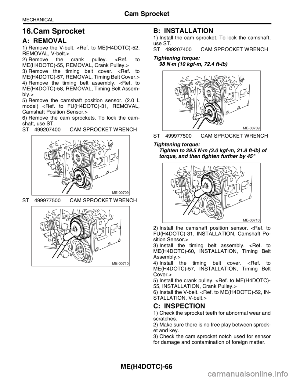
6) Remove the cam sprockets. To lock the cam-
shaft, use ST.
ST 499207400 CAM SPROCKET WRENCH
ST 499977500 CAM SPROCKET WRENCH
B: INSTALLATION
1) Install the cam sprocket. To lock the camshaft,
use ST.
ST 499207400 CAM SPROCKET WRENCH
Tightening torque:
98 N
⋅m (10 kgf-m, 72.4 ft-lb)
ST 499977500 CAM SPROCKET WRENCH
Tightening torque:
Tighten to 29.5 N
⋅m (3.0 kgf-m, 21.8 ft-lb) of
torque, and then tighten further by 45
°
2) Install the camshaft position sensor.
FU(H4DOTC)-31, INSTALLATION, Camshaft Po-
sition Sensor.>
3) Install the timing belt assembly.
ME(H4DOTC)-60, INSTALLATION, Timing Belt
Assembly.>
4) Install the timing belt cover.
ME(H4DOTC)-57, INSTALLATION, Timing Belt
Cover.>
5) Install the crank pulley.
55, INSTALLATION, Crank Pulley.>
6) Install the V-belt.
STALLATION, V-belt.>
C: INSPECTION
1) Check the sprocket teeth for abnormal wear and
scratches.
2) Make sure there is no free play between sprock-
et and key.
3) Check the cam sprocket notch used for sensor
for damage and contamination of foreign matter.
ME-00709
ME-00710
ME-00709
ME-00710
Page 1525 of 2870

ME(H4DOTC)-67
MECHANICAL
Crank Sprocket
17.Crank Sprocket
A: REMOVAL
1) Remove the V-belt.
REMOVAL, V-belt.>
2) Remove the crank pulley.
55, REMOVAL, Crank Pulley.>
3) Remove the timing belt cover.
ME(H4DOTC)-57, REMOVAL, Timing Belt Cover.>
4) Remove the timing belt assembly.
ME(H4DOTC)-58, REMOVAL, Timing Belt Assem-
bly.>
5) Remove the cam sprocket.
ME(H4DOTC)-67, REMOVAL, Cam Sprocket.>
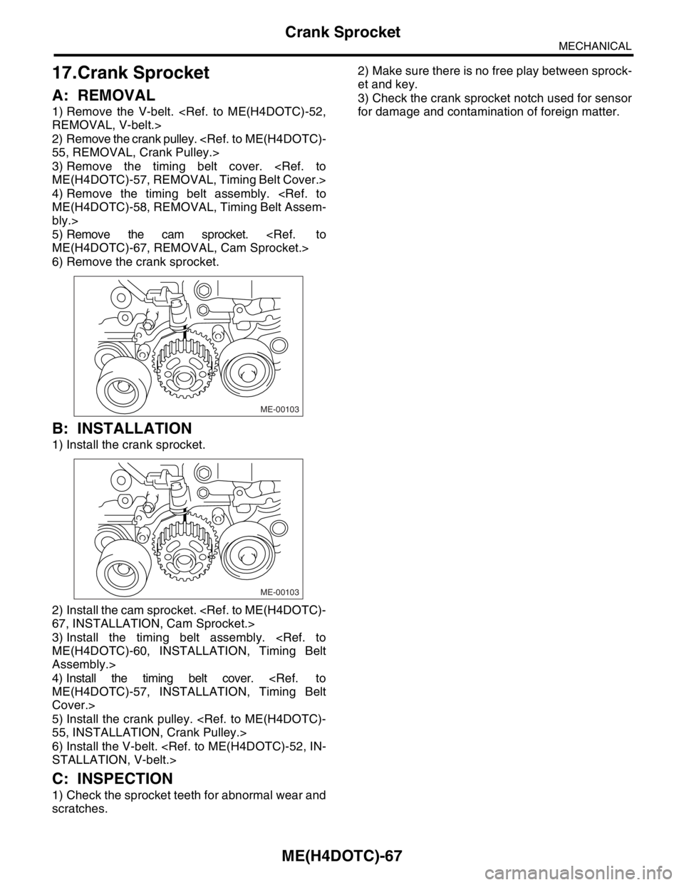
6) Remove the crank sprocket.
B: INSTALLATION
1) Install the crank sprocket.
2) Install the cam sprocket.
67, INSTALLATION, Cam Sprocket.>
3) Install the timing belt assembly.
ME(H4DOTC)-60, INSTALLATION, Timing Belt
Assembly.>
4) Install the timing belt cover.
ME(H4DOTC)-57, INSTALLATION, Timing Belt
Cover.>
5) Install the crank pulley.
55, INSTALLATION, Crank Pulley.>
6) Install the V-belt.
STALLATION, V-belt.>
C: INSPECTION
1) Check the sprocket teeth for abnormal wear and
scratches.2) Make sure there is no free play between sprock-
et and key.
3) Check the crank sprocket notch used for sensor
for damage and contamination of foreign matter.
ME-00103
ME-00103
Page 1589 of 2870

EX(H4DOTC)-3
EXHAUST
General Description
(1) Gasket (12) Exhaust manifold upper cover
(LH)Tightening torque: N·m (kgf-m, ft-lb)
(2) Exhaust manifold upper cover
(RH)T1: 19 (1.9, 13.7)
(13) Exhaust manifold lower cover (LH)T2: 7.5 (0.8, 5.5)
(3) Exhaust manifold (RH) (14) GasketT3: 35 (3.6, 26.0)
(4) Exhaust manifold lower cover
(RH)(15) Turbocharger joint pipeT4: 40 (4, 28.9)
(16) GasketT5:
INSTALLATION, Front Oxygen
(A/F) Sensor.> or
FU(H4DOTC 2.5)-37,
INSTALLATION, Front Oxygen
(A/F) Sensor.> (5) Front exhaust pipe upper cover (17) Front oxygen (A/F) sensor
(6) Front exhaust pipe upper insulator
(RH)(18) Exhaust temperature sensor
(19) Precatalytic converter
(7) Gasket (20) Front exhaust pipe upper insulator
(LH)
(8) Front exhaust pipeT6:
INSTALLATION, Exhaust
Temperature Sensor.> or
to FU(H4DOTC 2.5)-40,
INSTALLATION, Exhaust
Temperature Sensor.> (9) Front exhaust pipe lower insulator
(RH)(21) Front exhaust pipe lower insulator
(LH)
(10) Front exhaust pipe lower cover (22) Exhaust manifold (LH)
(11) Gasket
Page 1590 of 2870

EX(H4DOTC)-4
EXHAUST
General Description
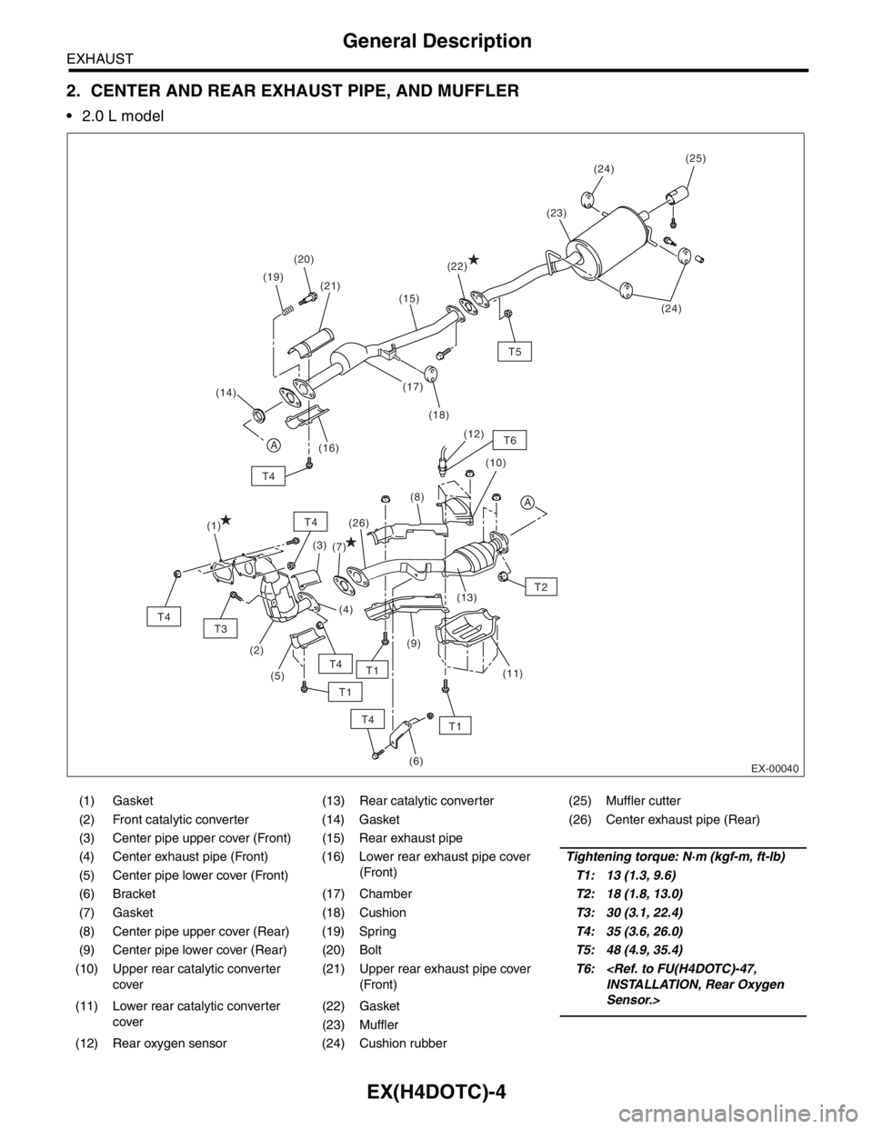
2. CENTER AND REAR EXHAUST PIPE, AND MUFFLER
2.0 L model
(1) Gasket (13) Rear catalytic converter (25) Muffler cutter
(2) Front catalytic converter (14) Gasket (26) Center exhaust pipe (Rear)
(3) Center pipe upper cover (Front) (15) Rear exhaust pipe
(4) Center exhaust pipe (Front) (16) Lower rear exhaust pipe cover
(Front)Tightening torque: N·m (kgf-m, ft-lb)
(5) Center pipe lower cover (Front)T1: 13 (1.3, 9.6)
(6) Bracket (17) ChamberT2: 18 (1.8, 13.0)
(7) Gasket (18) CushionT3: 30 (3.1, 22.4)
(8) Center pipe upper cover (Rear) (19) SpringT4: 35 (3.6, 26.0)
(9) Center pipe lower cover (Rear) (20) BoltT5: 48 (4.9, 35.4)
(10) Upper rear catalytic converter
cover(21) Upper rear exhaust pipe cover
(Front)T6:
INSTALLATION, Rear Oxygen
Sensor.>
(11) Lower rear catalytic converter
cover(22) Gasket
(23) Muffler
(12) Rear oxygen sensor (24) Cushion rubber
EX-00040
T4
A
T1
T5
T6
T4
(25)
(19)(24)
(24) (20)
(18) (17)
(16)(23)
(22)
(21)
A
(14)
T3
T4
T4
T4
(1)
(2)
(6)
(3)
(5)
T2 (8)(10) (12)
(11) (13)
(9) (26)
(7)
T1
T1
(15)
(4)