Page 1389 of 2870
FU(H4DOTC)-34
FUEL INJECTION (FUEL SYSTEM)
Throttle Position Sensor
9. Throttle Position Sensor
A: REMOVAL
1) Disconnect the ground cable from battery.
2) Remove the intercooler.
10, REMOVAL, Intercooler.>
3) Disconnect the connector from throttle position
sensor.
4) Remove the throttle position sensor holding
screws, and remove it.
B: INSTALLATION
Install in the reverse order of removal.
Tightening torque:
1.6 N
⋅m (0.16 kgf-m, 1.2 ft-lb)
FU-00009
FU-00065
FU-00066
FU-00066
Page 1390 of 2870
FU(H4DOTC)-35
FUEL INJECTION (FUEL SYSTEM)
Mass Air Flow and Intake Air Temperature Sensor
10.Mass Air Flow and Intake Air
Temperature Sensor
A: REMOVAL
1) Disconnect the ground cable from battery.
2) Disconnect the connector from mass air flow and
intake air temperature sensor.
3) Remove the mass air flow and intake air temper-
ature sensor.
B: INSTALLATION
Install in the reverse order of removal.
Tightening torque:
1.7 N
⋅m (0.17 kgf-m, 1.3 ft-lb)
FU-00009
FU-00067
Page 1391 of 2870
FU(H4DOTC)-36
FUEL INJECTION (FUEL SYSTEM)
Manifold Absolute Pressure Sensor
11.Manifold Absolute Pressure
Sensor
A: REMOVAL
1) Disconnect the ground cable from battery.
2) Remove the idle air control solenoid valve.
to FU(H4DOTC)-37, REMOVAL, Idle Air Control
Solenoid Valve.>
3) Disconnect the connectors from manifold abso-
lute pressure sensor.
4) Remove the manifold absolute pressure sensor
from throttle body.
B: INSTALLATION
Install in the reverse order of removal.
NOTE:
Replace the O-rings for manifold absolute pressure
sensor with new ones.
Tightening torque:
1.6 N
⋅m (0.16 kgf-m, 1.2 ft-lb)
FU-00009
FU-00068
Page 1397 of 2870
FU(H4DOTC)-42
FUEL INJECTION (FUEL SYSTEM)
Tumble Generator Valve Assembly
14.Tumble Generator Valve As-
sembly
A: REMOVAL
1) Release the fuel pressure.
54, RELEASING OF FUEL PRESSURE, OPERA-
TION, Fuel.>
2) Open the fuel filler flap lid, and then remove the
fuel filler cap.
3) Disconnect the ground cable from battery.
4) Remove the intake manifold.
FU(H4DOTC)-14, REMOVAL, Intake Manifold.>
5) Disconnect the connector from tumble generator
valve sensor.
6) Disconnect the connector from tumble generator
valve actuator.
7) Remove the fuel injector.
38, REMOVAL, Fuel Injector.>8) Remove the tumble generator valve body from
intake manifold.
B: INSTALLATION
Install in the reverse order of removal.
NOTE:
Always use new gaskets.
Tightening torque:
8.25 N
⋅m (0.84 kgf-m, 6.1 ft-lb)
FU-00009
FU-00617
FU-00616
FU-00053
FU-00053
Page 1400 of 2870

FU(H4DOTC)-45
FUEL INJECTION (FUEL SYSTEM)
Front Oxygen (A/F) Sensor
17.Front Oxygen (A/F) Sensor
A: REMOVAL
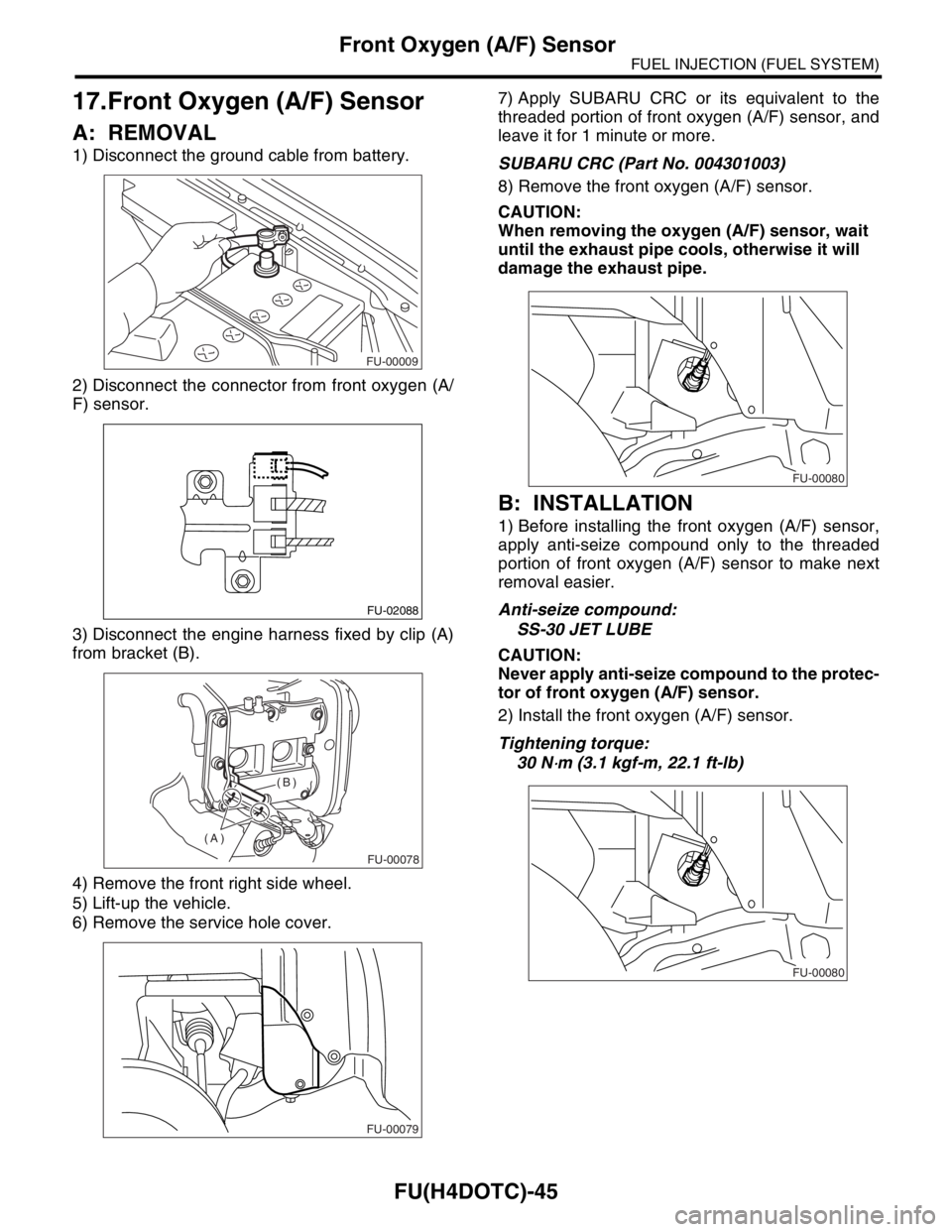
1) Disconnect the ground cable from battery.
2) Disconnect the connector from front oxygen (A/
F) sensor.
3) Disconnect the engine harness fixed by clip (A)
from bracket (B).
4) Remove the front right side wheel.
5) Lift-up the vehicle.
6) Remove the service hole cover.7) Apply SUBARU CRC or its equivalent to the
threaded portion of front oxygen (A/F) sensor, and
leave it for 1 minute or more.
SUBARU CRC (Part No. 004301003)
8) Remove the front oxygen (A/F) sensor.
CAUTION:
When removing the oxygen (A/F) sensor, wait
until the exhaust pipe cools, otherwise it will
damage the exhaust pipe.
B: INSTALLATION
1) Before installing the front oxygen (A/F) sensor,
apply anti-seize compound only to the threaded
portion of front oxygen (A/F) sensor to make next
removal easier.
Anti-seize compound:
SS-30 JET LUBE
CAUTION:
Never apply anti-seize compound to the protec-
tor of front oxygen (A/F) sensor.
2) Install the front oxygen (A/F) sensor.
Tightening torque:
30 N
⋅m (3.1 kgf-m, 22.1 ft-lb)
FU-00009
FU-02088
FU-00078
(A)(B)
FU-00079
FU-00080
FU-00080
Page 1401 of 2870
FU(H4DOTC)-46
FUEL INJECTION (FUEL SYSTEM)
Front Oxygen (A/F) Sensor
3) Install the service hole cover.
4) Lower the vehicle.
5) Install the front right side wheel.
6) Connect the engine harness with clip (A) to
bracket (B).
7) Connect the connector of front oxygen (A/F)
sensor.
8) Connect the battery ground cable to battery.
FU-00079
FU-00078
(A)(B)
FU-02088
FU-00009
Page 1402 of 2870

FU(H4DOTC)-47
FUEL INJECTION (FUEL SYSTEM)
Rear Oxygen Sensor
18.Rear Oxygen Sensor
A: REMOVAL
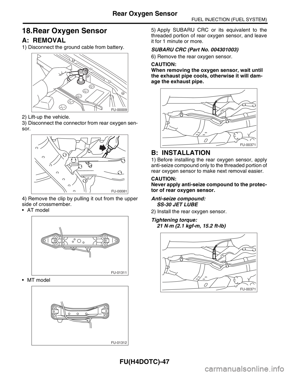
1) Disconnect the ground cable from battery.
2) Lift-up the vehicle.
3) Disconnect the connector from rear oxygen sen-
sor.
4) Remove the clip by pulling it out from the upper
side of crossmember.
AT model
MT model5) Apply SUBARU CRC or its equivalent to the
threaded portion of rear oxygen sensor, and leave
it for 1 minute or more.
SUBARU CRC (Part No. 004301003)
6) Remove the rear oxygen sensor.
CAUTION:
When removing the oxygen sensor, wait until
the exhaust pipe cools, otherwise it will dam-
age the exhaust pipe.
B: INSTALLATION
1) Before installing the rear oxygen sensor, apply
anti-seize compound only to the threaded portion of
rear oxygen sensor to make next removal easier.
CAUTION:
Never apply anti-seize compound to the protec-
tor of rear oxygen sensor.
Anti-seize compound:
SS-30 JET LUBE
2) Install the rear oxygen sensor.
Tightening torque:
21 N
⋅m (2.1 kgf-m, 15.2 ft-lb)
FU-00009
FU-00081
FU-01311
FU-01312
FU-00371
FU-00371
Page 1403 of 2870
FU(H4DOTC)-48
FUEL INJECTION (FUEL SYSTEM)
Rear Oxygen Sensor
3) Connect the connector to rear oxygen sensor.
4) Connect the clip to crossmember.
AT model
MT model
5) Lower the vehicle.
6) Connect the battery ground cable to battery.
FU-00081
FU-01311
FU-01312
FU-00009