2004 SUBARU FORESTER light
[x] Cancel search: lightPage 1536 of 2870

ME(H4DOTC)-78
MECHANICAL
Cylinder Head Assembly
1) Installation of valve spring and valve.
(1) Coat the stem of each valve with engine oil
and insert the valve into valve guide.
NOTE:
When inserting the valve into valve guide, use spe-
cial care not to damage the oil seal lip.
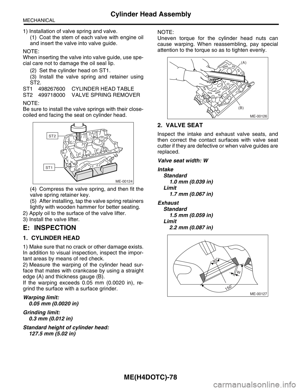
(2) Set the cylinder head on ST1.
(3) Install the valve spring and retainer using
ST2.
ST1 498267600 CYLINDER HEAD TABLE
ST2 499718000 VALVE SPRING REMOVER
NOTE:
Be sure to install the valve springs with their close-
coiled end facing the seat on cylinder head.
(4) Compress the valve spring, and then fit the
valve spring retainer key.
(5) After installing, tap the valve spring retainers
lightly with wooden hammer for better seating.
2) Apply oil to the surface of the valve lifter.
3) Install the valve lifter.
E: INSPECTION
1. CYLINDER HEAD
1) Make sure that no crack or other damage exists.
In addition to visual inspection, inspect the impor-
tant areas by means of red check.
2) Measure the warping of the cylinder head sur-
face that mates with crankcase by using a straight
edge (A) and thickness gauge (B).
If the warping exceeds 0.05 mm (0.0020 in), re-
grind the surface with a surface grinder.
Warping limit:
0.05 mm (0.0020 in)
Grinding limit:
0.3 mm (0.012 in)
Standard height of cylinder head:
127.5 mm (5.02 in)NOTE:
Uneven torque for the cylinder head nuts can
cause warping. When reassembling, pay special
attention to the torque so as to tighten evenly.
2. VALVE SEAT
Inspect the intake and exhaust valve seats, and
then correct the contact surfaces with valve seat
cutter if they are defective or when valve guides are
replaced.
Valve seat width: W
Intake
Standard
1.0 mm (0.039 in)
Limit
1.7 mm (0.067 in)
Exhaust
Standard
1.5 mm (0.059 in)
Limit
2.2 mm (0.087 in)
ME-00124
ST1
ST2
ME-00126
(A)
(B)
ME-00127
W
Page 1537 of 2870

ME(H4DOTC)-79
MECHANICAL
Cylinder Head Assembly
3. VALVE GUIDE
1) Check the clearance between valve guide and
stem. The clearance can be checked by measuring
the outside diameter of valve stem and the inside
diameter of valve guide with outside and inside mi-
crometers respectively.
Clearance between the valve guide and valve
stem:
Standard
Intake
0.030 — 0.057 mm (0.0012 — 0.0022 in)
Exhaust
0.040 — 0.067 mm (0.0016 — 0.0026 in)
Limit
0.15 mm (0.0059 in)
2) If the clearance between valve guide and stem
exceeds the limit, replace the valve guide or valve
itself whichever shows greater amount of wear.
See the following procedure for valve guide re-
placement.
Valve guide inner diameter:
6.000 — 6.012 mm (0.2362 — 0.2367 in)
Valve stem outer diameters:
Intake
5.955 — 5.970 mm (0.2344 — 0.2350 in)
Exhaust
5.945 — 5.960 mm (0.2341 — 0.2346 in)
(1) Place the cylinder head on ST1 with the
combustion chamber upward so that valve
guides enter the holes in ST1.
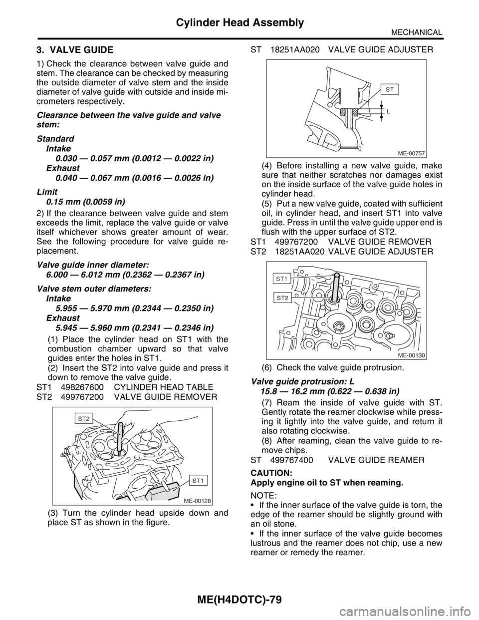
(2) Insert the ST2 into valve guide and press it
down to remove the valve guide.
ST1 498267600 CYLINDER HEAD TABLE
ST2 499767200 VALVE GUIDE REMOVER
(3) Turn the cylinder head upside down and
place ST as shown in the figure.ST 18251AA020 VALVE GUIDE ADJUSTER
(4) Before installing a new valve guide, make
sure that neither scratches nor damages exist
on the inside surface of the valve guide holes in
cylinder head.
(5) Put a new valve guide, coated with sufficient
oil, in cylinder head, and insert ST1 into valve
guide. Press in until the valve guide upper end is
flush with the upper surface of ST2.
ST1 499767200 VALVE GUIDE REMOVER
ST2 18251AA020 VALVE GUIDE ADJUSTER
(6) Check the valve guide protrusion.
Valve guide protrusion: L
15.8 — 16.2 mm (0.622 — 0.638 in)
(7) Ream the inside of valve guide with ST.
Gently rotate the reamer clockwise while press-
ing it lightly into the valve guide, and return it
also rotating clockwise.
(8) After reaming, clean the valve guide to re-
move chips.
ST 499767400 VALVE GUIDE REAMER
CAUTION:
Apply engine oil to ST when reaming.
NOTE:
If the inner surface of the valve guide is torn, the
edge of the reamer should be slightly ground with
an oil stone.
If the inner surface of the valve guide becomes
lustrous and the reamer does not chip, use a new
reamer or remedy the reamer.
ME-00128
ST1
ST2ME-00757
ST
L
ME-00130
ST1
ST2
Page 1568 of 2870

ME(H4DOTC)-108
MECHANICAL
Cylinder Block
4) Make sure that the piston pin can be inserted
into the piston pin hole with a thumb at 20°C (68°F).
Replace if defective.
Standard clearance between piston pin and
hole in piston:
Standard
0.004 — 0.008 mm (0.0002 — 0.0003 in)
Limit
0.020 mm (0.0008 in)
5) Check the circlip installation groove on piston for
burr (A). If necessary, remove the burr from groove
so that the piston pin can lightly move.
6) Check the piston pin circlip for distortion, cracks
and wear.4. PISTON RING
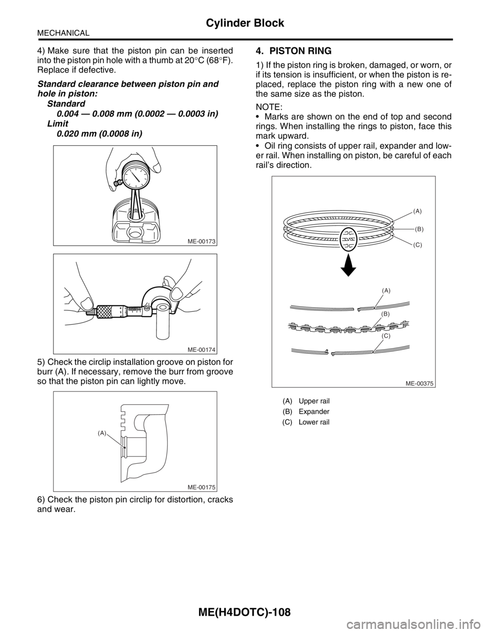
1) If the piston ring is broken, damaged, or worn, or
if its tension is insufficient, or when the piston is re-
placed, replace the piston ring with a new one of
the same size as the piston.
NOTE:
Marks are shown on the end of top and second
rings. When installing the rings to piston, face this
mark upward.
Oil ring consists of upper rail, expander and low-
er rail. When installing on piston, be careful of each
rail’s direction.
ME-00173
ME-00174
ME-00175
(A)
(A) Upper rail
(B) Expander
(C) Lower rail
ME-00375(A)
(B)
(C)
(A)
(B)
(C)
Page 1583 of 2870

ME(H4DOTC)-123
MECHANICAL
Engine Noise
26.Engine Noise
A: INSPECTION
NOTE*:
When disconnecting the fuel injector connector, Malfunction Indicator Light illuminates and DTC is stored in
ECM memory.
Therefore, carry out the CLEAR MEMORY MODE
necting the fuel injector connector.
Type of sound Condition Possible cause
Regular clicking soundSound increases as engine
speed increases. Valve mechanism is defective.
Incorrect valve clearance
Worn valve rocker
Worn camshaft
Broken valve spring
Heavy and dull clankOil pressure is low. Worn crankshaft main bearing
Worn connecting rod bearing (big end)
Oil pressure is normal. Loose flywheel mounting bolts
Damaged engine mounting
High-pitched clank (Spark
knock)Sound is noticeable when
accelerating with an overload. Ignition timing advanced
Accumulation of carbon inside combustion chamber
Wrong heat range of spark plug
Improper octane number of gasoline
Clank when engine speed is
medium (1,000 to 2,000 rpm).Sound is reduced when fuel
injector connector of noisy cyl-
inder is disconnected.
(NOTE*) Worn crankshaft main bearing
Worn bearing at crankshaft end of connecting rod
Knocking sound when engine
is operating under idling speed
and engine is warmSound is reduced when fuel
injector connector of noisy cyl-
inder is disconnected.
(NOTE*) Worn cylinder liner and piston ring
Broken or stuck piston ring
Worn piston pin and hole at piston end of connecting rod
Sound is not reduced if each
fuel injector connector is dis-
connected in turn. (NOTE*) Unusually worn valve lifter
Worn cam gear
Worn camshaft journal bore in crankcase
Squeaky sound — Insufficient generator lubrication
Rubbing sound — Defective generator brush and rotor contact
Gear scream when starting
engine— Defective ignition starter switch
Worn gear and starter pinion
Sound like polishing glass with
a dry cloth— Loose drive belt
Defective water pump shaft
Hissing sound — Loss of compression
Air leakage in air intake system, hoses, connections or mani-
folds
Timing belt noise — Loose timing belt
Belt contacting case/adjacent part
Valve tappet noise — Incorrect valve clearance
Page 1622 of 2870

IG(H4DOTC)-6
IGNITION
Spark Plug
5) Disconnect the connector from ignition coil.
6) Remove the ignition coil.
7) Remove the spark plugs with the spark plug
sockets.
B: INSTALLATION
1. RH SIDE
Install in the reverse order of removal.
Tightening torque (Spark plug):
21 N
⋅m (2.1 kgf-m, 15.2 ft-lb)
Tightening torque (Ignition coil):
16 N
⋅m (1.6 kgf-m, 11.7 ft-lb)
NOTE:
The above torque should be only applied to new
spark plugs without oil on their threads.
In case their threads are lubricated, the torque
should be reduced by approx. 1/3 of the specified
torque in order to avoid over-stressing.
2. LH SIDE
Install in the reverse order of removal.
Tightening torque (Spark plug):
21 N
⋅m (2.1 kgf-m, 15.2 ft-lb)
Tightening torque (Ignition coil):
16 N
⋅m (1.6 kgf-m, 11.7 ft-lb)
NOTE:
The above torque should be only applied to new
spark plugs without oil on their threads.
In case their threads are lubricated, the torque
should be reduced by approx. 1/3 of the specified
torque in order to avoid over-stressing.
C: INSPECTION
Check the electrodes and inner and ceramic insu-
lator of plugs, noting the type of deposits and the
degree of electrode erosion.
1) Normal:
Brown to grayish-tan deposits and slight electrode
wear indicates correct spark plug heat range.
FU-01308
IG-00008
IG-00009
(A) Electrode gap
(B) Carbon accumulation or wear
(C) Cracks
(D) Damage
(E) Damaged gasket
IG-00010
(A)
(B)
(C)
(D)
(E)
IG-00011
Page 1623 of 2870

IG(H4DOTC)-7
IGNITION
Spark Plug
2) Carbon fouled:
Dry fluffy carbon deposits on insulator and elec-
trode are mostly caused by slow speed driving in
city, weak ignition, too rich fuel mixture, dirty air
cleaner, etc.
It is advisable to replace with plugs having hotter
heat range.
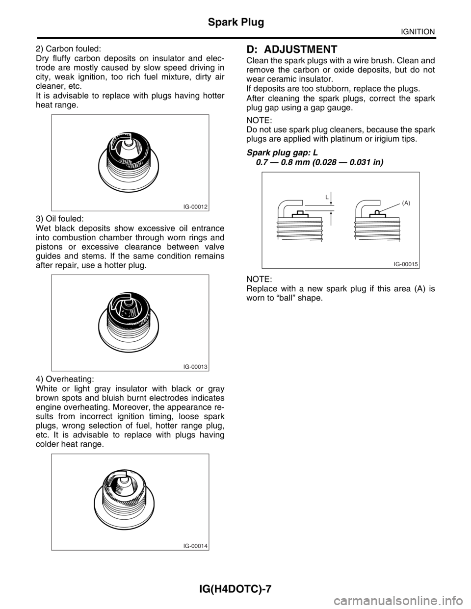
3) Oil fouled:
Wet black deposits show excessive oil entrance
into combustion chamber through worn rings and
pistons or excessive clearance between valve
guides and stems. If the same condition remains
after repair, use a hotter plug.
4) Overheating:
White or light gray insulator with black or gray
brown spots and bluish burnt electrodes indicates
engine overheating. Moreover, the appearance re-
sults from incorrect ignition timing, loose spark
plugs, wrong selection of fuel, hotter range plug,
etc. It is advisable to replace with plugs having
colder heat range.D: ADJUSTMENT
Clean the spark plugs with a wire brush. Clean and
remove the carbon or oxide deposits, but do not
wear ceramic insulator.
If deposits are too stubborn, replace the plugs.
After cleaning the spark plugs, correct the spark
plug gap using a gap gauge.
NOTE:
Do not use spark plug cleaners, because the spark
plugs are applied with platinum or irigium tips.
Spark plug gap: L
0.7 — 0.8 mm (0.028 — 0.031 in)
NOTE:
Replace with a new spark plug if this area (A) is
worn to “ball” shape.
IG-00012
IG-00013
IG-00014
IG-00015
L
(A)
Page 1631 of 2870

ENGINE (DIAGNOSTIC)
EN(H4DOTC)
Page
1. Basic Diagnostics Procedure ......................................................................2
2. Check List for Interview ...............................................................................4
3. General Description ....................................................................................6
4. Electrical Component Location ...................................................................9
5. Engine Control Module (ECM) I/O Signal .................................................23
6. Engine Condition Data ..............................................................................27
7. Transmission Control Module (TCM) I/O Signal .......................................28
8. Data Link Connector .................................................................................29
9. OBD-II General Scan Tool ........................................................................30
10. Subaru Select Monitor...............................................................................33
11. Read Diagnostic Trouble Code (DTC) ......................................................39
12. Inspection Mode ........................................................................................40
13. Drive Cycle ................................................................................................45
14. Clear Memory Mode..................................................................................47
15. Compulsory Valve Operation Check Mode ...............................................48
16. Malfunction Indicator Light ........................................................................50
17. Diagnostics for Engine Starting Failure .....................................................59
18. List of Diagnostic Trouble Code (DTC) .....................................................74
19. Diagnostic Procedure with Diagnostic Trouble Code (DTC) .....................80
20. General Diagnostic Table........................................................................295
Page 1632 of 2870

EN(H4DOTC)-2
ENGINE (DIAGNOSTIC)
Basic Diagnostics Procedure
1. Basic Diagnostics Procedure
A: PROCEDURE
1. ENGINE
Step Check Yes No
1 CHECK ENGINE START FAILURE.
1) Ask the customer when and how the trou-
ble occurred using the interview check list.
2) Start the engine.Does the engine start? Go to step 2.Inspection using
“Diagnostics for
Engine Start Fail-
ure”.
Diagnostics for
Engine Starting
Fai lu r e.>
2 CHECK ILLUMINATION OF MALFUNCTION
INDICATOR LIGHT.Does malfunction indicator
light illuminate?Go to step 3.Inspection using
“General Diagnos-
tic Table”.
295, General Diag-
nostic Table.>
3 CHECK INDICATION OF DTC ON DISPLAY.
1) Turn the ignition switch to OFF.
2) Connect the Subaru Select Monitor or the
OBD-II general scan tool to data link connec-
tor.
3) Turn the ignition switch to ON and the Sub-
aru Select Monitor or OBD-II general scan tool
switch to ON.
4) Read the DTC on the Subaru Select Moni-
tor or OBD-II general scan tool.Does the Subaru Select Moni-
tor or OBD-II general scan tool
indicate DTC?Record the
DTC.Repair the
trouble cause.
List of Diagnostic
Trouble Code
(DTC).> Go to
step 4.Repair the related
parts.
N
OTE:
If DTC is not shown
on display although
the malfunction in-
dicator light illumi-
nates, perform the
diagnostics for mal-
function indicator
light circuit or com-
bination meter.
Malfunction Indica-
tor Light.>
4 PERFORM THE DIAGNOSIS.
1) Perform clear memory mode.
2) Perform the “INSPECTION MODE”.
tor or OBD-II general scan tool
indicate DTC?Check on “Diag-
nostic Chart with
Diagnostic Trou-
ble Code (DTC)”
Diagnostic Proce-
dure with Diagnos-
tic Trouble Code
(DTC).>Finish the diagno-
sis.