2004 SUBARU FORESTER coolant
[x] Cancel search: coolantPage 757 of 2870
PM-20
PERIODIC MAINTENANCE SERVICE
Cooling System
11.Cooling System
A: INSPECTION
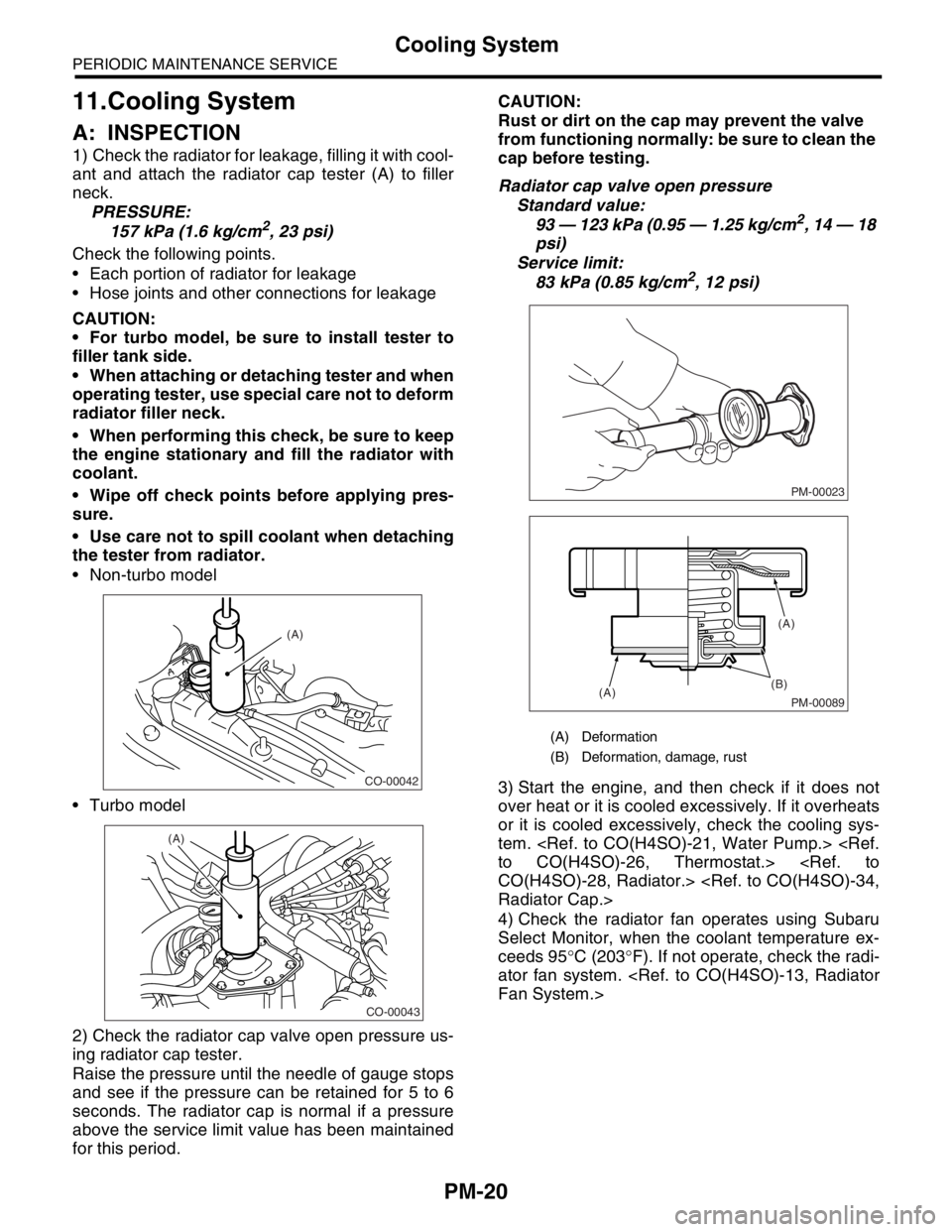
1) Check the radiator for leakage, filling it with cool-
ant and attach the radiator cap tester (A) to filler
neck.
PRESSURE:
157 kPa (1.6 kg/cm
2, 23 psi)
Check the following points.
Each portion of radiator for leakage
Hose joints and other connections for leakage
CAUTION:
For turbo model, be sure to install tester to
filler tank side.
When attaching or detaching tester and when
operating tester, use special care not to deform
radiator filler neck.
When performing this check, be sure to keep
the engine stationary and fill the radiator with
coolant.
Wipe off check points before applying pres-
sure.
Use care not to spill coolant when detaching
the tester from radiator.
Non-turbo model
Turbo model
2) Check the radiator cap valve open pressure us-
ing radiator cap tester.
Raise the pressure until the needle of gauge stops
and see if the pressure can be retained for 5 to 6
seconds. The radiator cap is normal if a pressure
above the service limit value has been maintained
for this period.CAUTION:
Rust or dirt on the cap may prevent the valve
from functioning normally: be sure to clean the
cap before testing.
Radiator cap valve open pressure
Standard value:
93 — 123 kPa (0.95 — 1.25 kg/cm2, 14 — 18
psi)
Service limit:
83 kPa (0.85 kg/cm
2, 12 psi)
3) Start the engine, and then check if it does not
over heat or it is cooled excessively. If it overheats
or it is cooled excessively, check the cooling sys-
tem.
4) Check the radiator fan operates using Subaru
Select Monitor, when the coolant temperature ex-
ceeds 95°C (203°F). If not operate, check the radi-
ator fan system.
CO-00042
(A)
CO-00043
(A)
(A) Deformation
(B) Deformation, damage, rust
PM-00023
PM-00089
(B)
(A)(A)
Page 758 of 2870
PM-21
PERIODIC MAINTENANCE SERVICE
Engine Coolant
12.Engine Coolant
A: REPLACEMENT
1. REPLACEMENT OF ENGINE COOLANT
WARNING:
The radiator is of the pressurized type. Do not
attempt to open the radiator cap immediately
after the engine has been stopped.
1) Lift-up the vehicle.
2) Remove the under cover.
3) Place a container under drain pipe.
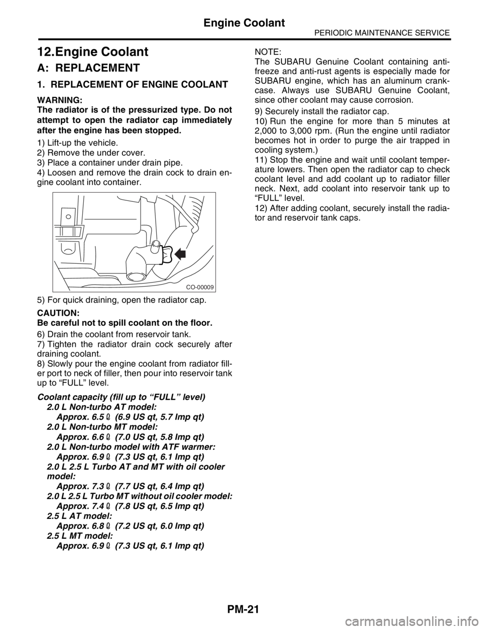
4) Loosen and remove the drain cock to drain en-
gine coolant into container.
5) For quick draining, open the radiator cap.
CAUTION:
Be careful not to spill coolant on the floor.
6) Drain the coolant from reservoir tank.
7) Tighten the radiator drain cock securely after
draining coolant.
8) Slowly pour the engine coolant from radiator fill-
er port to neck of filler, then pour into reservoir tank
up to “FULL” level.
Coolant capacity (fill up to “FULL” level)
2.0 L Non-turbo AT model:
Approx. 6.52 (6.9 US qt, 5.7 Imp qt)
2.0 L Non-turbo MT model:
Approx. 6.62 (7.0 US qt, 5.8 Imp qt)
2.0 L Non-turbo model with ATF warmer:
Approx. 6.92 (7.3 US qt, 6.1 Imp qt)
2.0 L 2.5 L Turbo AT and MT with oil cooler
model:
Approx. 7.32 (7.7 US qt, 6.4 Imp qt)
2.0 L 2.5 L Turbo MT without oil cooler model:
Approx. 7.42 (7.8 US qt, 6.5 Imp qt)
2.5 L AT model:
Approx. 6.82 (7.2 US qt, 6.0 Imp qt)
2.5 L MT model:
Approx. 6.92 (7.3 US qt, 6.1 Imp qt)NOTE:
The SUBARU Genuine Coolant containing anti-
freeze and anti-rust agents is especially made for
SUBARU engine, which has an aluminum crank-
case. Always use SUBARU Genuine Coolant,
since other coolant may cause corrosion.
9) Securely install the radiator cap.
10) Run the engine for more than 5 minutes at
2,000 to 3,000 rpm. (Run the engine until radiator
becomes hot in order to purge the air trapped in
cooling system.)
11) Stop the engine and wait until coolant temper-
ature lowers. Then open the radiator cap to check
coolant level and add coolant up to radiator filler
neck. Next, add coolant into reservoir tank up to
“FULL” level.
12) After adding coolant, securely install the radia-
tor and reservoir tank caps.
CO-00009
Page 759 of 2870
PM-22
PERIODIC MAINTENANCE SERVICE
Engine Coolant
2. RELATIONSHIP OF SUBARU COOLANT
CONCENTRATION AND FREEZING TEM-
PERATURE
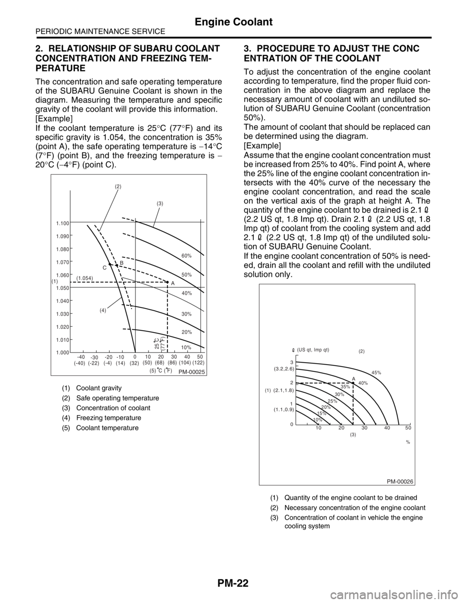
The concentration and safe operating temperature
of the SUBARU Genuine Coolant is shown in the
diagram. Measuring the temperature and specific
gravity of the coolant will provide this information.
[Example]
If the coolant temperature is 25°C (77°F) and its
specific gravity is 1.054, the concentration is 35%
(point A), the safe operating temperature is −14°C
(7°F) (point B), and the freezing temperature is −
20°C (−4°F) (point C).
3. PROCEDURE TO ADJUST THE CONC
ENTRATION OF THE COOLANT
To adjust the concentration of the engine coolant
according to temperature, find the proper fluid con-
centration in the above diagram and replace the
necessary amount of coolant with an undiluted so-
lution of SUBARU Genuine Coolant (concentration
50%).
The amount of coolant that should be replaced can
be determined using the diagram.
[Example]
Assume that the engine coolant concentration must
be increased from 25% to 40%. Find point A, where
the 25% line of the engine coolant concentration in-
tersects with the 40% curve of the necessary the
engine coolant concentration, and read the scale
on the vertical axis of the graph at height A. The
quantity of the engine coolant to be drained is 2.12
(2.2 US qt, 1.8 Imp qt). Drain 2.12 (2.2 US qt, 1.8
Imp qt) of coolant from the cooling system and add
2.12 (2.2 US qt, 1.8 Imp qt) of the undiluted solu-
tion of SUBARU Genuine Coolant.
If the engine coolant concentration of 50% is need-
ed, drain all the coolant and refill with the undiluted
solution only.
(1) Coolant gravity
(2) Safe operating temperature
(3) Concentration of coolant
(4) Freezing temperature
(5) Coolant temperature
PM-00025
60%
(1.054)
1.000 1.010 1.020
1.030
1.040
1.050
1.060
1.070 1.080 1.090
1.100
(5) (4)(3) (2)
(1)B
A C
-40
(-40) (-22)(-4)
(14)(32)(50) (68) (86)
( F)(104) (122) -30-20 -1001020304050
(77 F)
50%
40%
30%
20%
25 C10%
C
(1) Quantity of the engine coolant to be drained
(2) Necessary concentration of the engine coolant
(3) Concentration of coolant in vehicle the engine
cooling system
PM-00026
10 0 12 3
(1.1,0.9) (2.1,1.8)(3.2,2.6)
10%15%25%
20%30%35%40%45%
A
20 30 40 50
% (3)(2)
(1)(US qt, Imp qt)
Page 783 of 2870

FUEL INJECTION (FUEL SYSTEM)
FU(H4SO)
Page
1. General Description ....................................................................................2
2. Throttle Body .............................................................................................13
3. Intake Manifold ..........................................................................................14
4. Engine Coolant Temperature Sensor........................................................25
5. Crankshaft Position Sensor.......................................................................26
6. Camshaft Position Sensor.........................................................................27
7. Knock Sensor ............................................................................................28
8. Throttle Position Sensor ............................................................................29
9. Manifold Absolute Pressure Sensor ..........................................................31
10. Intake Air Temperature Sensor .................................................................32
11. Idle Air Control Solenoid Valve .................................................................33
12. EGR Valve ................................................................................................34
13. Fuel Injector ..............................................................................................35
14. Front Oxygen (A/F) Sensor .......................................................................40
15. Rear Oxygen Sensor.................................................................................42
16. Engine Control Module (ECM) ..................................................................44
17. Main Relay ................................................................................................45
18. Fuel Pump Relay.......................................................................................46
19. Fuel ...........................................................................................................47
20. Fuel Tank ..................................................................................................48
21. Fuel Filler Pipe ..........................................................................................51
22. Fuel Pump .................................................................................................55
23. Fuel Level Sensor .....................................................................................57
24. Fuel Sub Level Sensor ..............................................................................58
25. Fuel Filter ..................................................................................................60
26. Fuel Cut Valve...........................................................................................61
27. Fuel Damper Valve ...................................................................................62
28. Fuel Delivery, Return and Evaporation Lines............................................63
29. Fuel System Trouble in General ...............................................................66
Page 795 of 2870
FU(H4SO)-13
FUEL INJECTION (FUEL SYSTEM)
Throttle Body
2. Throttle Body
A: REMOVAL
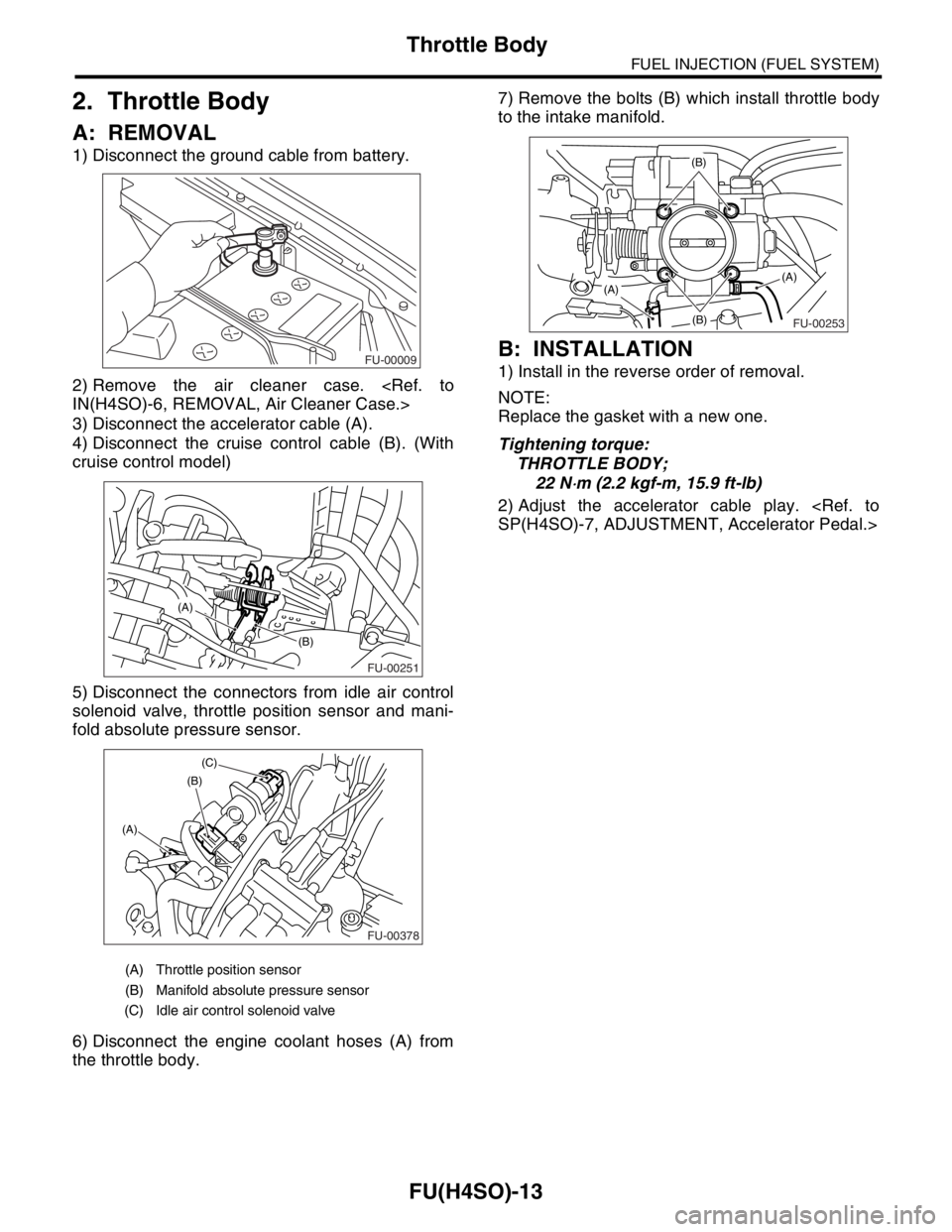
1) Disconnect the ground cable from battery.
2) Remove the air cleaner case.
3) Disconnect the accelerator cable (A).
4) Disconnect the cruise control cable (B). (With
cruise control model)
5) Disconnect the connectors from idle air control
solenoid valve, throttle position sensor and mani-
fold absolute pressure sensor.
6) Disconnect the engine coolant hoses (A) from
the throttle body.7) Remove the bolts (B) which install throttle body
to the intake manifold.
B: INSTALLATION
1) Install in the reverse order of removal.
NOTE:
Replace the gasket with a new one.
Tightening torque:
THROTTLE BODY;
22 N
⋅m (2.2 kgf-m, 15.9 ft-lb)
2) Adjust the accelerator cable play.
(A) Throttle position sensor
(B) Manifold absolute pressure sensor
(C) Idle air control solenoid valve
FU-00009
FU-00251
(B)
(A)
FU-00378
(B)
(A)(C)
FU-00253
(B)
(B)
(A)(A)
Page 797 of 2870
FU(H4SO)-15
FUEL INJECTION (FUEL SYSTEM)
Intake Manifold
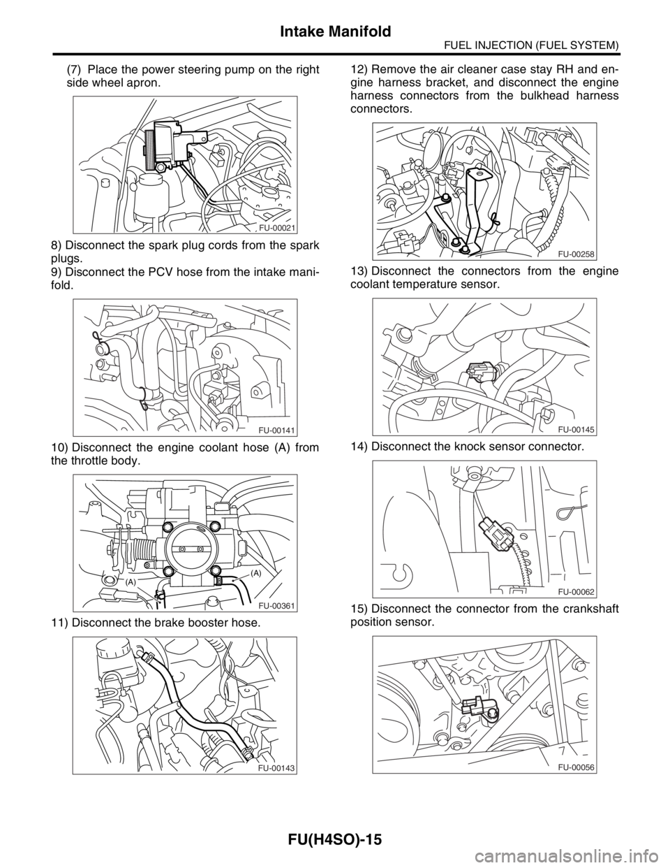
(7) Place the power steering pump on the right
side wheel apron.
8) Disconnect the spark plug cords from the spark
plugs.
9) Disconnect the PCV hose from the intake mani-
fold.
10) Disconnect the engine coolant hose (A) from
the throttle body.
11) Disconnect the brake booster hose.12) Remove the air cleaner case stay RH and en-
gine harness bracket, and disconnect the engine
harness connectors from the bulkhead harness
connectors.
13) Disconnect the connectors from the engine
coolant temperature sensor.
14) Disconnect the knock sensor connector.
15) Disconnect the connector from the crankshaft
position sensor.
FU-00021
FU-00141
FU-00361
(A)(A)
FU-00143
FU-00258
FU-00145
FU-00062
FU-00056
Page 799 of 2870
FU(H4SO)-17
FUEL INJECTION (FUEL SYSTEM)
Intake Manifold
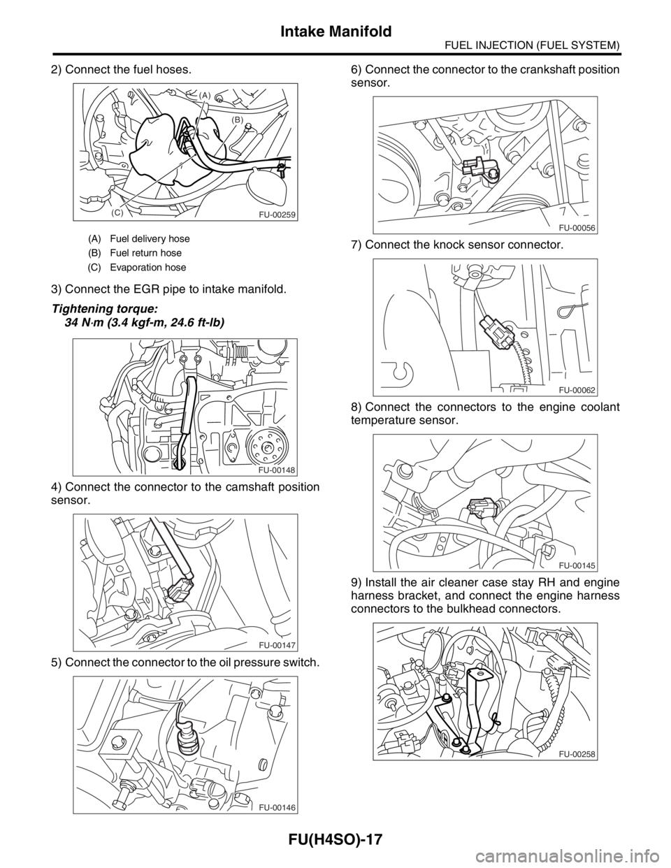
2) Connect the fuel hoses.
3) Connect the EGR pipe to intake manifold.
Tightening torque:
34 N
⋅m (3.4 kgf-m, 24.6 ft-lb)
4) Connect the connector to the camshaft position
sensor.
5) Connect the connector to the oil pressure switch.6) Connect the connector to the crankshaft position
sensor.
7) Connect the knock sensor connector.
8) Connect the connectors to the engine coolant
temperature sensor.
9) Install the air cleaner case stay RH and engine
harness bracket, and connect the engine harness
connectors to the bulkhead connectors.
(A) Fuel delivery hose
(B) Fuel return hose
(C) Evaporation hose
(B) (A)
(C)
FU-00259
FU-00148
FU-00147
FU-00146
FU-00056
FU-00062
FU-00145
FU-00258
Page 800 of 2870
FU(H4SO)-18
FUEL INJECTION (FUEL SYSTEM)
Intake Manifold
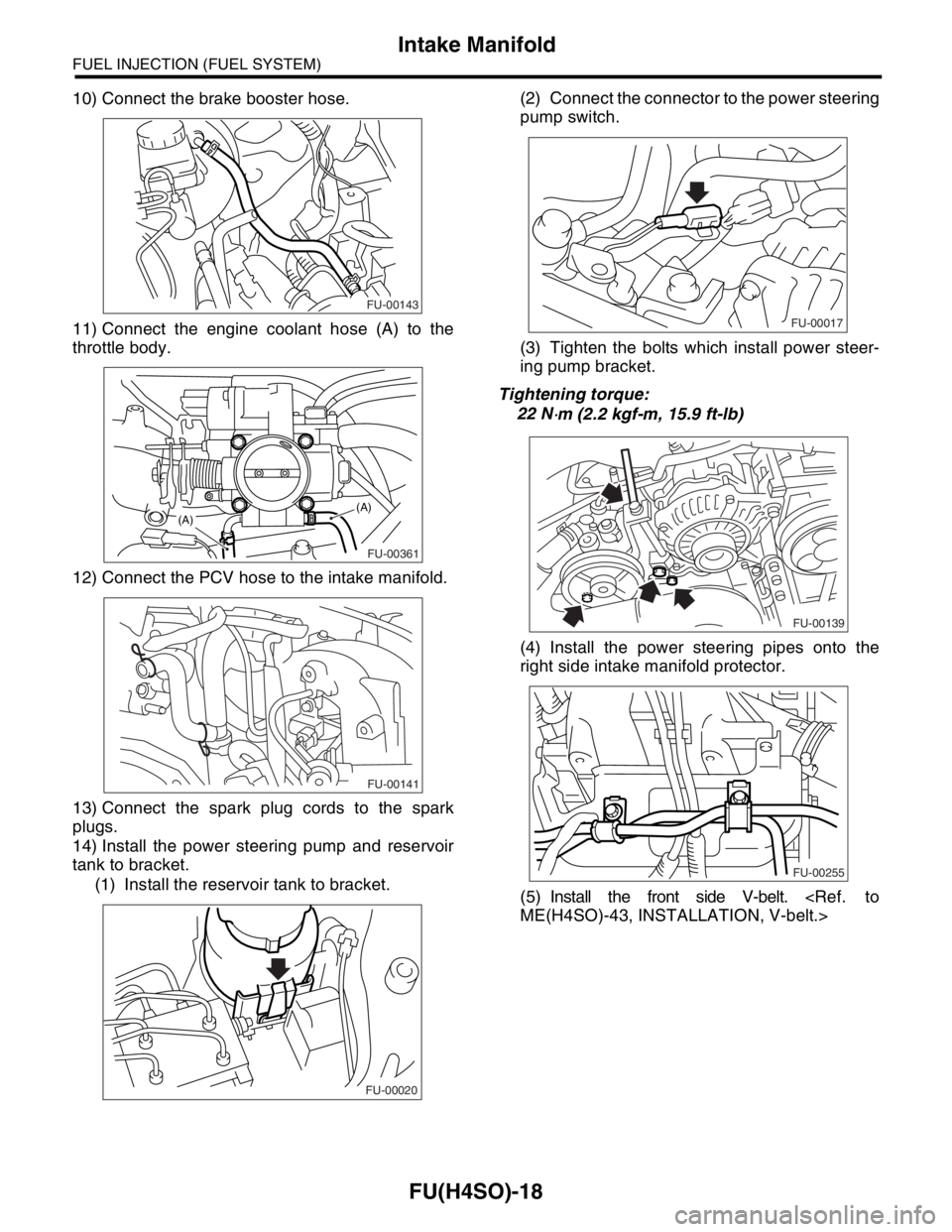
10) Connect the brake booster hose.
11) Connect the engine coolant hose (A) to the
throttle body.
12) Connect the PCV hose to the intake manifold.
13) Connect the spark plug cords to the spark
plugs.
14) Install the power steering pump and reservoir
tank to bracket.
(1) Install the reservoir tank to bracket.(2) Connect the connector to the power steering
pump switch.
(3) Tighten the bolts which install power steer-
ing pump bracket.
Tightening torque:
22 N
⋅m (2.2 kgf-m, 15.9 ft-lb)
(4) Install the power steering pipes onto the
right side intake manifold protector.
(5) Install the front side V-belt.
FU-00143
FU-00361
(A)(A)
FU-00141
FU-00020
FU-00017
FU-00139
FU-00255