Page 1931 of 2870

FUEL INJECTION (FUEL SYSTEM)
FU(H4DOTC 2.5)
Page
1. General Description ....................................................................................2
2. Throttle Body .............................................................................................13
3. Intake Manifold ..........................................................................................14
4. Engine Coolant Temperature Sensor........................................................26
5. Crankshaft Position Sensor.......................................................................27
6. Camshaft Position Sensor.........................................................................28
7. Knock Sensor ............................................................................................29
8. Mass Air Flow and Intake Air Temperature Sensor ..................................30
9. Manifold Absolute Pressure Sensor ..........................................................31
10. Fuel Injector ..............................................................................................32
11. Tumble Generator Valve Assembly ..........................................................33
12. Tumble Generator Valve Actuator.............................................................34
13. Wastegate Control Solenoid Valve ...........................................................35
14. Front Oxygen (A/F) Sensor .......................................................................36
15. Rear Oxygen Sensor.................................................................................38
16. Exhaust Temperature Sensor ...................................................................40
17. Engine Control Module (ECM) ..................................................................41
18. Main Relay ................................................................................................42
19. Fuel Pump Relay.......................................................................................43
20. Fuel Pump Control Unit .............................................................................44
21. Fuel ...........................................................................................................45
22. Fuel Tank ..................................................................................................46
23. Fuel Filler Pipe ..........................................................................................48
24. Fuel Pump .................................................................................................52
25. Fuel Level Sensor .....................................................................................54
26. Fuel Sub Level Sensor ..............................................................................55
27. Fuel Filter ..................................................................................................57
28. Fuel Cut Valve...........................................................................................58
29. Fuel Damper Valve ...................................................................................59
30. Fuel Delivery, Return and Evaporation Lines............................................60
31. Fuel System Trouble in General ...............................................................63
Page 1966 of 2870
FU(H4DOTC 2.5)-36
FUEL INJECTION (FUEL SYSTEM)
Front Oxygen (A/F) Sensor
14.Front Oxygen (A/F) Sensor
A: REMOVAL
1) Disconnect the ground cable from battery.
2) Disconnect the connector from the front oxygen
(A/F) sensor.
3) Disconnect the engine harness fixed by clip (A)
from the bracket (B).
4) Remove the front right side wheel.
5) Lift-up the vehicle.
6) Remove the service hole cover.7) Apply SUBARU CRC or its equivalent to the
threaded portion of front oxygen (A/F) sensor, and
leave it for one minute or more.
SUBARU CRC (Part No. 004301003)
8) Remove the front oxygen (A/F) sensor.
CAUTION:
When removing the front oxygen (A/F) sensor,
wait until exhaust pipe cools; otherwise, it will
damage exhaust pipe.
FU-00009
FU-01229
FU-00078
(A)(B)
FU-00783
FU-00080
Page 1967 of 2870
FU(H4DOTC 2.5)-37
FUEL INJECTION (FUEL SYSTEM)
Front Oxygen (A/F) Sensor
B: INSTALLATION
1) Before installing front oxygen (A/F) sensor, ap-
ply anti-seize compound only to the threaded por-
tion of front oxygen (A/F) sensor to make the next
removal easier.
Anti-seize compound:
SS-30 JET LUBE
CAUTION:
Never apply anti-seize compound to protector
of front oxygen (A/F) sensor.
2) Install the front oxygen (A/F) sensor.
Tightening torque:
30 N·m (3.1 kgf-m, 22.1 ft-lb)
3) Install the service hole cover.
4) Lower the vehicle.
5) Install the front right side wheel.
6) Connect the engine harness to the bracket (B)
using clips (A).7) Connect the connector of front oxygen (A/F)
sensor.
8) Connect the battery ground cable to battery.
FU-00080
FU-00783
FU-00078
(A)(B)
FU-01229
FU-00009
Page 1968 of 2870

FU(H4DOTC 2.5)-38
FUEL INJECTION (FUEL SYSTEM)
Rear Oxygen Sensor
15.Rear Oxygen Sensor
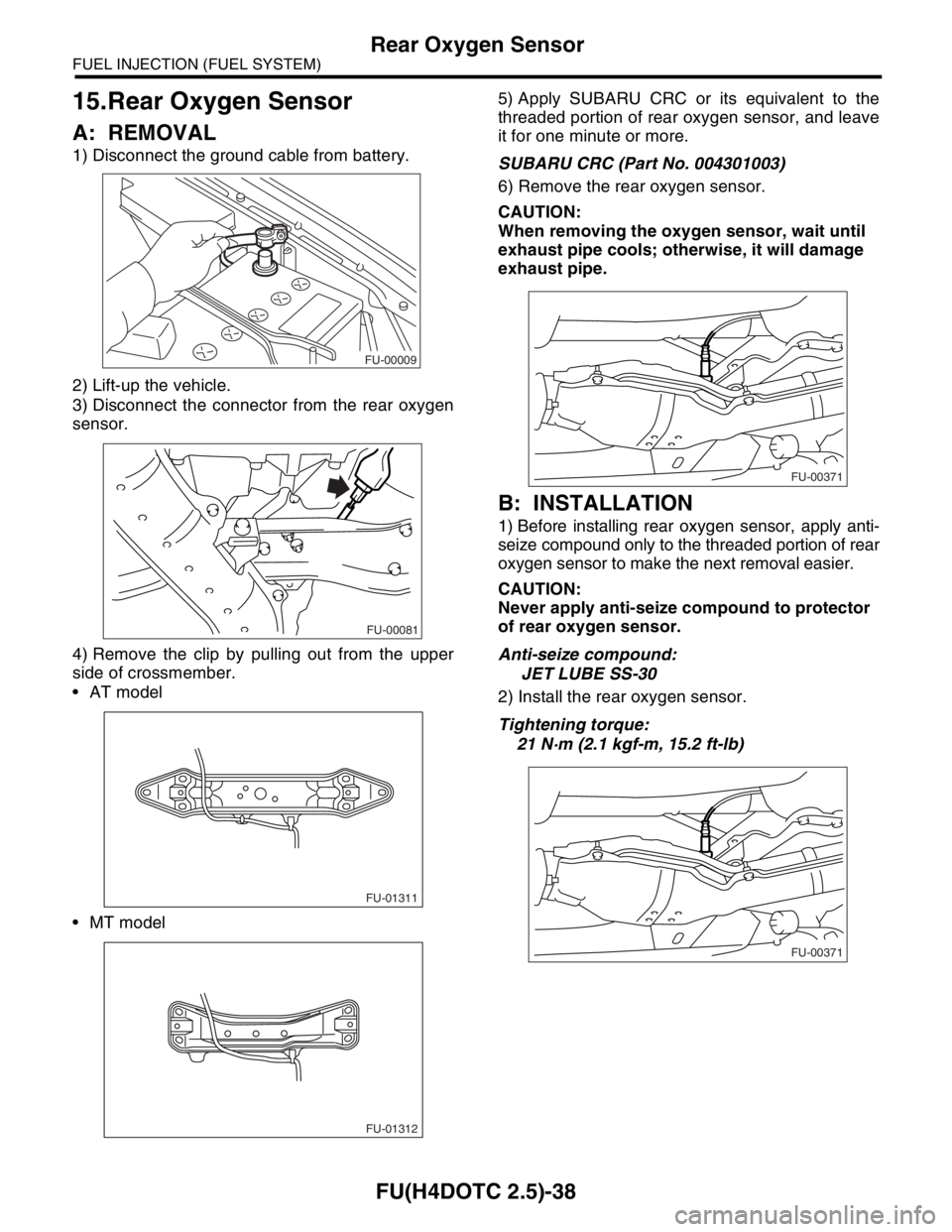
A: REMOVAL
1) Disconnect the ground cable from battery.
2) Lift-up the vehicle.
3) Disconnect the connector from the rear oxygen
sensor.
4) Remove the clip by pulling out from the upper
side of crossmember.
AT model
MT model5) Apply SUBARU CRC or its equivalent to the
threaded portion of rear oxygen sensor, and leave
it for one minute or more.
SUBARU CRC (Part No. 004301003)
6) Remove the rear oxygen sensor.
CAUTION:
When removing the oxygen sensor, wait until
exhaust pipe cools; otherwise, it will damage
exhaust pipe.
B: INSTALLATION
1) Before installing rear oxygen sensor, apply anti-
seize compound only to the threaded portion of rear
oxygen sensor to make the next removal easier.
CAUTION:
Never apply anti-seize compound to protector
of rear oxygen sensor.
Anti-seize compound:
JET LUBE SS-30
2) Install the rear oxygen sensor.
Tightening torque:
21 N·m (2.1 kgf-m, 15.2 ft-lb)
FU-00009
FU-00081
FU-01311
FU-01312
FU-00371
FU-00371
Page 1969 of 2870
FU(H4DOTC 2.5)-39
FUEL INJECTION (FUEL SYSTEM)
Rear Oxygen Sensor
3) Connect the connector to the rear oxygen sensor.
4) Connect the clip to the crossmember.
AT model
MT model
5) Lower the vehicle.
6) Connect the battery ground cable to battery.
FU-00081
FU-01311
FU-01312
FU-00009
Page 2035 of 2870
EN(H4DOTC 2.5)-11
ENGINE (DIAGNOSTIC)
Electrical Component Location
(1) Front oxygen (A/F) sensor (3) Exhaust gas temperature sensor (5) Rear oxygen sensor
(2) Precatalytic converter (4) Front catalytic converter (6) Rear catalytic converter
EN-02351 (1)
(5)
(6)
(4)
(2)(3)
Page 2041 of 2870

EN(H4DOTC 2.5)-17
ENGINE (DIAGNOSTIC)
Engine Control Module (ECM) I/O Signal
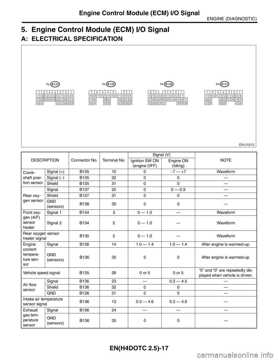
5. Engine Control Module (ECM) I/O Signal
A: ELECTRICAL SPECIFICATION
DESCRIPTION Connector No. Terminal No.Signal (V)
NOTE
Ignition SW ON
(engine OFF)Engine ON
(Idling)
Crank-
shaft posi-
tion sensorSignal (+) B135 10 0−7 — +7 Waveform
Signal (−) B135 22 0 0 —
Shield B135 31 0 0 —
Rear oxy-
gen sensorSignal B137 25 0 0 — 0.9 —
Shield B137 31 0 0 —
GND
(sensors)B136 35 0 0 —
Fr o nt ox y-
gen (A/F)
sensor
heaterSignal 1 B134 3 0 — 1.0 — Waveform
Signal 2 B134 2 0 — 1.0 — Waveform
Rear oxygen sensor
heater signalB135 2 0 — 1.0 — Waveform
Engine
coolant
tempera-
ture sen-
sorSignal B136 14 1.0 — 1.4 1.0 — 1.4 After engine is warmed-up.
GND
(sensors)B136 35 0 0 After engine is warmed-up.
Vehicle speed signal B135 26 0 or 5 0 or 5“5” and “0” are repeatedly dis-
played when vehicle is driven.
Air flow
sensorSignal B136 23 — 0.3 — 4.5 —
Shield B136 32 0 0 —
GND B136 31 0 0 —
Intake air temperature
sensor signalB136 13 0.3 — 4.6 0.3 — 4.6 —
Exhaust
gas tem-
perature
sensorSignal B136 24 — — —
GND
(sensors)B136 35 0 0 —
EN-01812
B134
5 6 7
8 21
9 43
10
24 2223 2511 12 13 14 15
26 27
28 16 17
18 19 20 21
33 34 29
32 3031
B136
5 6
7 8 21
9 43
10
24 2223 2511 12 13
14 15
26 27
28 16
17 18 19 20 21
33 3429
3230
31 35
B135
5 6 7
8 21
9 43
10
24 2223 2511 12 13 14 15
26 27
28 16 17 18 19
20 21
29 30 31 32 33 34 35
B137
5 6 7
8 21
9 43
10
22 2311 12 13 14 15
24 25
26 16 17
18 19 20 21
27 28 29 30 31
To
To To
To
Page 2043 of 2870

EN(H4DOTC 2.5)-19
ENGINE (DIAGNOSTIC)
Engine Control Module (ECM) I/O Signal
Radiator fan relay 2 con-
trolB135 24ON: 0.5, or less
OFF: 10 — 13ON: 0.5, or less
OFF: 13 — 14Model with A/C only
Malfunction indicator
lightB134 17 — —Light “ON”: 1, or less
Light “OFF”: 10 — 14
Engine speed output B134 23 — 0 — 13, or more Waveform
Purge control solenoid
valveB134 14ON: 1, or less
OFF: 10 — 13ON: 1, or less
OFF: 13 — 14Wavefor m
Manifold
absolute
pressure
sensorSignal B136 22 1.7 — 2.4 1.1 — 1.6
— Pow er
supplyB136 16 5 5
GND
(sensors)B136 35 0 0
Small light switch B137 12ON: 0
OFF: 10 — 13ON: 0
OFF: 13 — 14—
Blower fan switch B137 13ON: 0
OFF: 10 — 13ON: 0
OFF: 13 — 14—
Rear defogger switch B137 11ON: 0
OFF: 10 — 13ON: 0
OFF: 13 — 14—
Power steering oil pres-
sure switchB137 10 10 — 13ON: 0
OFF: 13 — 14—
Front oxygen (A/F) sen-
sor signal (+)B134 33 2.8 — 3.2 2.8 — 3.2 —
Front oxygen (A/F) sen-
sor signal (−)B134 26 2.4 — 2.7 2.4 — 2.7 —
Front oxygen (A/F) sen-
sor shieldB134 25 0 0 —
SSM/GST communica-
tion lineB137 20 1 ← → 41 ← → 4—
GND (injector) B137 7 0 0 —
GND (ignition system) B135 12 0 0 —
GND (power supply)B135 4 0 0 —
B135 1 0 0 —
GND (control system)B137 1 0 0 —
B137 2 0 0 —
GND (Front oxygen (A/F)
sensor heater 1)B134 7 0 0 —
GND (Front oxygen (A/F)
sensor heater 2)B134 6 0 0 —
Camshaft position sen-
sor (LH)B135 8 0 — 0.9ON: 0
OFF: 4.7 — 5.3Wavefor m
Camshaft position sen-
sor (RH)B135 9 0 — 0.9ON: 0
OFF: 4.7 — 5.3Wavefor m
Fuel level sensor B136 20 0.12 — 4.75 0.12 — 4.75 —
Electronic
throttle
controlMain B136 180.64 — 0.72
Fully opens:
3.960.64 — 0.72
(After engine is
warmed-up.)Fully closed: 0.6 Fully opens:
3.96
Sub B136 291.51 — 1.58
Fully opens:
4.171.51 — 1.58
(After engine is
warmed-up)Fully closed: 1.48 Fully opens:
4.17
Pow er
supplyB136 16 5 5 —
GND
(sensor)B137 3 0 0 — DESCRIPTION Connector No. Terminal No.Signal (V)
NOTE
Ignition SW ON
(engine OFF)Engine ON
(Idling)