Page 1863 of 2870

EN(H4DOTC)-230
ENGINE (DIAGNOSTIC)
Diagnostic Procedure with Diagnostic Trouble Code (DTC)
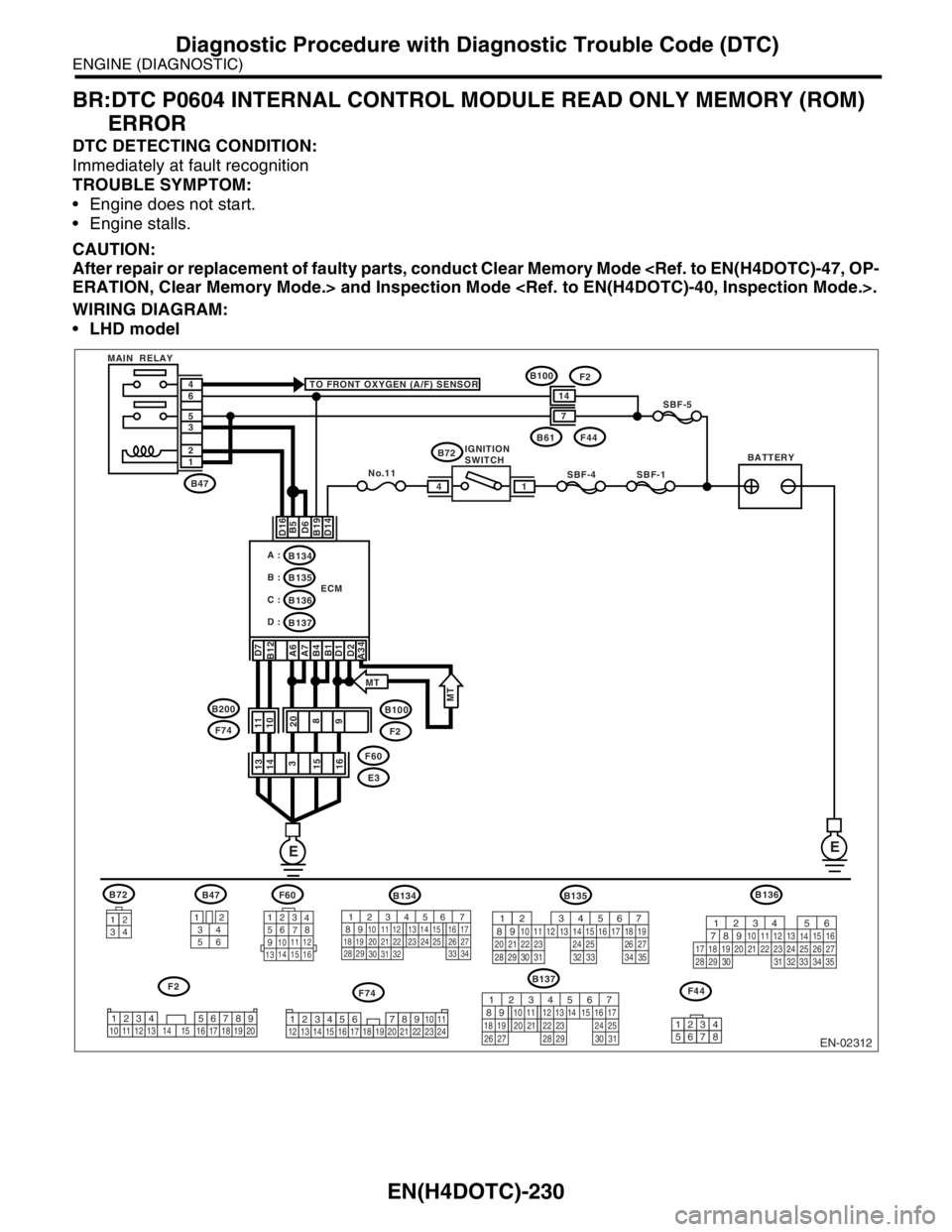
BR:DTC P0604 INTERNAL CONTROL MODULE READ ONLY MEMORY (ROM)
ERROR
DTC DETECTING CONDITION:
Immediately at fault recognition
TROUBLE SYMPTOM:
Engine does not start.
Engine stalls.
CAUTION:
After repair or replacement of faulty parts, conduct Clear Memory Mode
ERATION, Clear Memory Mode.> and Inspection Mode .
WIRING DIAGRAM:
LHD model
EN-02312
F74
B72
34
12
BATTERYIGNITION
SWITCH MAIN RELAY
SBF-4SBF-1
SBF-5
B72 TO FRONT OXYGEN (A/F) SENSOR
D16 D7
B12
A6
A7
B4
B1
D1
D2
A34B5
D6
B19
D14
No.11
B61F44
B47
B100
F2
E3 F60 1 2 3 5 6 4
ECM
EE
14
B134
B137 B135 A :
B :
C :B136
D :
14
7
3412
56
123
4
56
78
9
1011 12
1314 15 16
F60B47
B137
F2
B100F2
11
10
20
8
9 13
14
3
15
16
B135
F44
567
82 1
94 310
24 22 23 2511 12 13 14 15
26 27
2816 17 18 19
20 21
29 30 31 32 33 34 35
12345678
34
12 8910 11
12 13 14 15 16 17 18 19 20 21 22 23 2456 71234 5678910 11 12 13 14 15 16 17 18 19 20
567
82 1
94 310
22 23 11 12 13 14 15
24 25
2616 17
18 19 20 21
27 28 29 30 31
F74 B200
MT
MT
B134
56 7
82 1
94 310
24 22 23 25 11 12 13 14 15
26 27
2816 17
18 19 20 21
33 34 29
32 30 31
B136
56
782 1
94 310
24 22 23 2511 12 13
1415
26 27
2816
17 18 19 20 21
33 34 29
32 30
31 35
Page 1905 of 2870
EN(H4DOTC)-272
ENGINE (DIAGNOSTIC)
Diagnostic Procedure with Diagnostic Trouble Code (DTC)
CN:DTC P1152 O2 SENSOR CIRCUIT RANGE/PERFORMANCE (LOW) (BANK 1
SENSOR 1)
DTC DETECTING CONDITION:
Two consecutive driving cycles with fault
CAUTION:
After repair or replacement of faulty parts, conduct Clear Memory Mode
ERATION, Clear Memory Mode.> and Inspection Mode .
WIRING DIAGRAM:
EN-02320
BATTERYMAIN RELAYSBF-5
B47 1 2 3 5 4 6
E
E
B100F2
14LHD
RHD
LHD
RHD
B100
F2
F60
E3
20
3
RHD
RHD6
72
3
33
26
25
ECMB134
: LHD: LHD
B21: RHD: RHD
1
4 2
3
B262
FRONT OXYGEN
(A/F) SENSOR
3412
56
123
4
56
78
9
1011 12
1314 15 16
B21
F60
B47
B262
B134
F2
LHD LHD
1234
56 7
82 1
94 310
24 22 23 25 11 12 13 14 15
26 27
2816 17
18 19 20 21
33 34 29
32 30 31
1234 5678910 11 12 13 14 15 16 17 18 19 20
: LHDE2: RHD
Page 1906 of 2870

EN(H4DOTC)-273
ENGINE (DIAGNOSTIC)
Diagnostic Procedure with Diagnostic Trouble Code (DTC)
Step Check Yes No
1 CHECK HARNESS BETWEEN ECM AND
FRONT OXYGEN (A/F) SENSOR CONNEC-
TOR.
1) Turn the ignition switch to OFF.
2) Disconnect the connector from ECM and
front oxygen (A/F) sensor connector.
3) Measure the resistance of harness
between ECM and front oxygen (A/F) sensor
connector.
Connector & terminal
(B134) No. 26 — (B18) No. 3:
(B134) No. 33 — (B18) No. 4:Is the resistance less than 1
Ω?Go to step 2.Repair the har-
ness and connec-
tor.
N
OTE:
In this case repair
the following:
Check harness
between ECM and
front oxygen (A/F)
sensor connector.
Poor contact in
front oxygen (A/F)
sensor connector
Poor contact in
ECM connector.
2 CHECK POOR CONTACT.
Check poor contact in front oxygen (A/F) sen-
sor connector.Is there any poor contact in
front oxygen (A/F) sensor con-
nector?Repair the poor
contact in front
oxygen (A/F) sen-
sor connector.Replace the front
oxygen (A/F) sen-
sor.
FU(H4DOTC)-45,
Front Oxygen (A/
F) Sensor.>
Page 1907 of 2870
EN(H4DOTC)-274
ENGINE (DIAGNOSTIC)
Diagnostic Procedure with Diagnostic Trouble Code (DTC)
CO:DTC P1153 O2 SENSOR CIRCUIT RANGE/PERFORMANCE (HIGH) (BANK 1
SENSOR 1)
DTC DETECTING CONDITION:
Two consecutive driving cycles with fault
CAUTION:
After repair or replacement of faulty parts, conduct Clear Memory Mode
ERATION, Clear Memory Mode.> and Inspection Mode .
WIRING DIAGRAM:
EN-02320
BATTERYMAIN RELAYSBF-5
B47 1 2 3 5 4 6
E
E
B100F2
14LHD
RHD
LHD
RHD
B100
F2
F60
E3
20
3
RHD
RHD6
72
3
33
26
25
ECMB134
: LHD: LHD
B21: RHD: RHD
1
4 2
3
B262
FRONT OXYGEN
(A/F) SENSOR
3412
56
123
4
56
78
9
1011 12
1314 15 16
B21
F60
B47
B262
B134
F2
LHD LHD
1234
56 7
82 1
94 310
24 22 23 25 11 12 13 14 15
26 27
2816 17
18 19 20 21
33 34 29
32 30 31
1234 5678910 11 12 13 14 15 16 17 18 19 20
: LHDE2: RHD
Page 1908 of 2870

EN(H4DOTC)-275
ENGINE (DIAGNOSTIC)
Diagnostic Procedure with Diagnostic Trouble Code (DTC)
Step Check Yes No
1 CHECK HARNESS BETWEEN ECM AND
FRONT OXYGEN (A/F) SENSOR CONNEC-
TOR.
1) Turn the ignition switch to OFF.
2) Disconnect the connector from ECM and
front oxygen (A/F) sensor.
3) Measure the resistance of harness
between ECM connector and chassis ground.
Connector & terminal
(B134) No. 33 — Chassis ground:Is the resistance more than 1
MΩ?Go to step 2.Repair the ground
short circuit in har-
ness between
ECM and front
oxygen (A/F) sen-
sor connector.
2 CHECK HARNESS BETWEEN ECM AND
FRONT OXYGEN (A/F) SENSOR CONNEC-
TOR.
Measure the resistance of harness between
ECM connector and chassis ground.
Connector & terminal
(B134) No. 26 — Chassis ground:Is the resistance more than 1
MΩ?Go to step 3.Repair the ground
short circuit in har-
ness between
ECM and front
oxygen (A/F) sen-
sor connector.
3 CHECK OUTPUT SIGNAL FOR ECM.
1) Connect the connector to ECM and front
oxygen (A/F) sensor.
2) Turn the ignition switch to ON.
3) Measure the voltage between ECM con-
nector and chassis ground.
Connector & terminal
(B134) No. 33 (+) — Chassis ground (
−):Is the voltage more than 4.5 V? Go to step 4.Go to step 5.
4 CHECK OUTPUT SIGNAL FOR ECM.
Measure the voltage between ECM connector
and chassis ground.
Connector & terminal
(B134) No. 33 (+) — Chassis ground (
−):Is the voltage more than 10 V? Repair the battery
short circuit in har-
ness between
ECM and front
oxygen (A/F) sen-
sor connector.After
repair, replace the
ECM.
FU(H4DOTC)-50,
Engine Control
Module (ECM).>Repair the poor
contact in ECM
connector.
5 CHECK OUTPUT SIGNAL FOR ECM.
Measure the voltage between ECM connector
and chassis ground.
Connector & terminal
(B134) No. 19 (+) — Chassis ground (
−):Is the voltage more than 4.95
V?Go to step 6.Replace the front
oxygen (A/F) sen-
sor.
FU(H4DOTC)-45,
Front Oxygen (A/
F) Sensor.>
6 CHECK OUTPUT SIGNAL FOR ECM.
Measure the voltage between ECM connector
and chassis ground.
Connector & terminal
(B134) No. 26 (+) — Chassis ground (
−):Is the voltage more than 10 V? Repair the battery
short circuit in har-
ness between
ECM and front
oxygen (A/F) sen-
sor connector.After
repair, replace the
ECM.
FU(H4DOTC)-50,
Engine Control
Module (ECM).>Repair the poor
contact in ECM
connector.
Page 1916 of 2870
EN(H4DOTC)-283
ENGINE (DIAGNOSTIC)
Diagnostic Procedure with Diagnostic Trouble Code (DTC)
Step Check Yes No
1 CHECK ANY OTHER DTC ON DISPLAY.Is any other DTC displayed? Inspect the rele-
vant DTC using
“List of Diagnostic
Trouble Code
(DTC)”.
EN(H4DOTC)-74,
List of Diagnostic
Trouble Code
(DTC).>
N
OTE:
In this case, it is
not necessary to
inspect DTC
P1544.Go to step 2.
2 CHECK EXHAUST SYSTEM.
Check exhaust system parts.
NOTE:
Check the following items:
Loose installation of exhaust manifold
Cracks or hole of exhaust manifold
Loose installation of front oxygen (A/F) sen-
sorIs there a fault in exhaust sys-
tem?Repair or replace
failure, then
replace the precat-
alytic converter.Contact the SUB-
ARU dealer.
NOTE:
Inspection by DTM
is required, be-
cause probable
cause is deteriora-
tion of multiple
parts.
Page 1917 of 2870

EN(H4DOTC)-284
ENGINE (DIAGNOSTIC)
Diagnostic Procedure with Diagnostic Trouble Code (DTC)
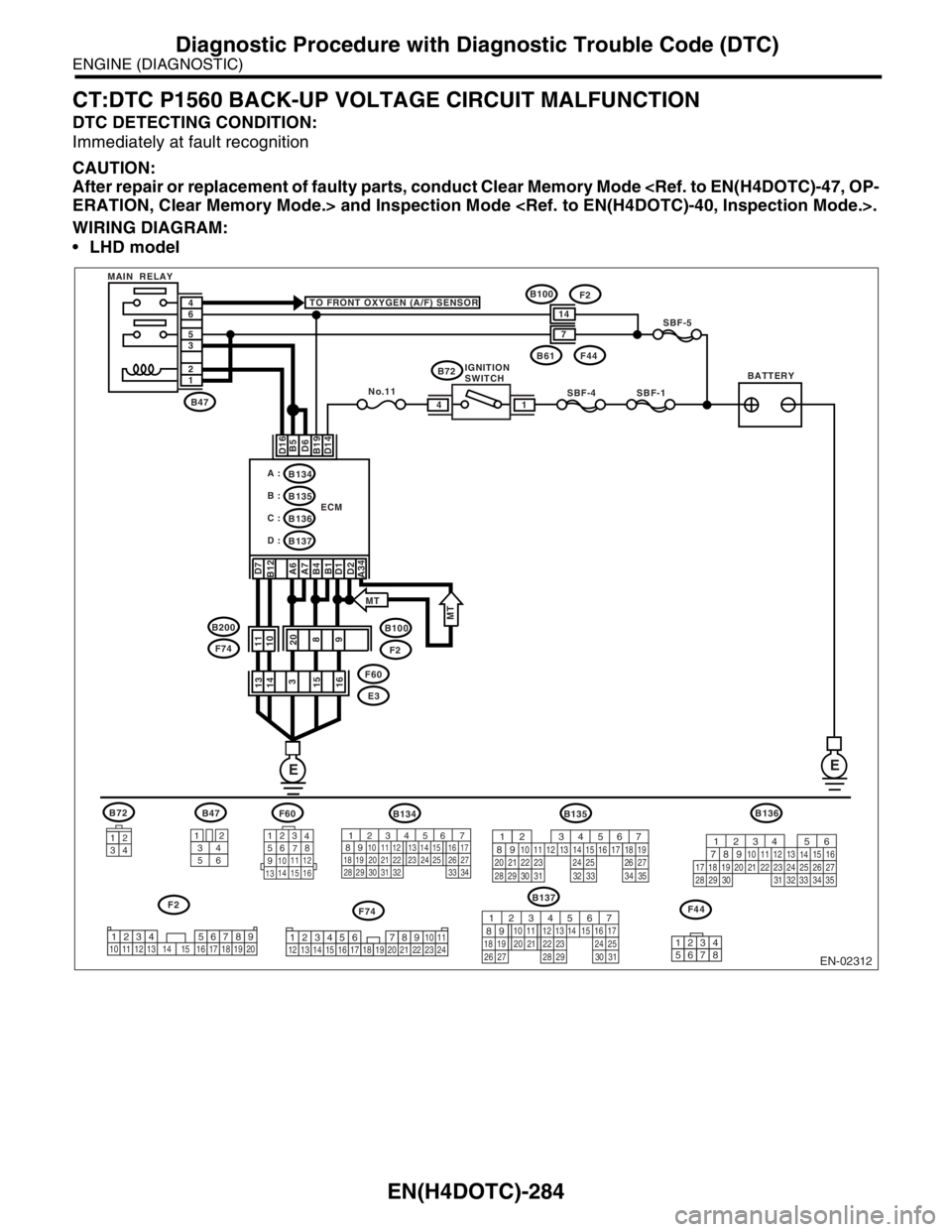
CT:DTC P1560 BACK-UP VOLTAGE CIRCUIT MALFUNCTION
DTC DETECTING CONDITION:
Immediately at fault recognition
CAUTION:
After repair or replacement of faulty parts, conduct Clear Memory Mode
ERATION, Clear Memory Mode.> and Inspection Mode .
WIRING DIAGRAM:
LHD model
EN-02312
F74
B72
34
12
BATTERYIGNITION
SWITCH MAIN RELAY
SBF-4SBF-1
SBF-5
B72 TO FRONT OXYGEN (A/F) SENSOR
D16 D7
B12
A6
A7
B4
B1
D1
D2
A34B5
D6
B19
D14
No.11
B61F44
B47
B100
F2
E3 F60 1 2 3 5 6 4
ECM
EE
14
B134
B137 B135 A :
B :
C :B136
D :
14
7
3412
56
123
4
56
78
9
1011 12
1314 15 16
F60B47
B137
F2
B100F2
11
10
20
8
9 13
14
3
15
16
B135
F44
567
82 1
94 310
24 22 23 2511 12 13 14 15
26 27
2816 17 18 19
20 21
29 30 31 32 33 34 35
12345678
34
12 8910 11
12 13 14 15 16 17 18 19 20 21 22 23 2456 71234 5678910 11 12 13 14 15 16 17 18 19 20
567
82 1
94 310
22 23 11 12 13 14 15
24 25
2616 17
18 19 20 21
27 28 29 30 31
F74 B200
MT
MT
B134
56 7
82 1
94 310
24 22 23 25 11 12 13 14 15
26 27
2816 17
18 19 20 21
33 34 29
32 30 31
B136
56
782 1
94 310
24 22 23 2511 12 13
1415
26 27
2816
17 18 19 20 21
33 34 29
32 30
31 35
Page 1928 of 2870

EN(H4DOTC)-295
ENGINE (DIAGNOSTIC)
General Diagnostic Table
20.General Diagnostic Table
A: INSPECTION
1. ENGINE
NOTE:
Malfunction of parts other than those listed is also possible.
General.>
Symptom Problem parts
1. Engine stalls during idling.1) Idle air control solenoid valve
2) Manifold absolute pressure sensor
3) Mass air flow and intake air temperature sensor
4) Ignition parts (*1)
5) Engine coolant temperature sensor (*2)
6) Crankshaft position sensor (*3)
7) Camshaft position sensor (*3)
8) Fuel injection parts (*4)
2. Rough idling1) Idle air control solenoid valve
2) Manifold absolute pressure sensor
3) Mass air flow and intake air temperature sensor
4) Engine coolant temperature sensor (*2)
5) Ignition parts (*1)
6) Air intake system (*5)
7) Fuel injection parts (*4)
8) Throttle position sensor
9) Crankshaft position sensor (*3)
10) Camshaft position sensor (*3)
11) Oxygen sensor
12) Fuel pump and fuel pump relay
3. Engine does not return to idle.1) Idle air control solenoid valve
2) Engine coolant temperature sensor
3) Accelerator cable (*6)
4) Throttle position sensor
5) Manifold absolute pressure sensor
6) Mass air flow sensor
4. Poor acceleration1) Manifold absolute pressure sensor
2) Mass air flow and intake air temperature sensor
3) Throttle position sensor
4) Fuel injection parts (*4)
5) Fuel pump and fuel pump relay
6) Engine coolant temperature sensor (*2)
7) Crankshaft position sensor (*3)
8) Camshaft position sensor (*3)
9) A/C switch and A/C cut relay
10) Engine torque control signal circuit
11) Ignition parts (*1)
5. Engine stalls or engine sags or hesitates at
acceleration.1) Manifold absolute pressure sensor
2) Mass air flow and intake air temperature sensor
3) Engine coolant temperature sensor (*2)
4) Crankshaft position sensor (*3)
5) Camshaft position sensor (*3)
6) Purge control solenoid valve
7) Fuel injection parts (*4)
8) Throttle position sensor
9) Fuel pump and fuel pump relay