2004 NISSAN TERRANO brake fluid
[x] Cancel search: brake fluidPage 1168 of 1833
BRAKE SYSTEM
SECTION
BR
CONTENTS
PRECAUTIONS AND PREPARATION ............................3
Supplement Restraint System (SRS) ²AIR BAG²
and ²SEAT BELT PRE-TENSIONER² .........................3
Precautions ..................................................................3
Preparation ..................................................................4
CHECK AND ADJUSTMENT ..........................................5
Checking Brake Fluid Level.........................................5
Checking Brake Line ...................................................5
Changing Brake Fluid ..................................................5
Brake Burnishing Procedure........................................5
BRAKE HYDRAULIC LINE .............................................6
Bleeding Brake System ...............................................8
Removal .......................................................................9
Inspection.....................................................................9
Installation ....................................................................9
LOAD SENSING VALVE ...............................................10
Removal and Installation ...........................................10
Removal ..................................................................... 11
Installation .................................................................. 11
Inspection and Adjustment ........................................12
BRAKE PEDAL AND BRACKET ..................................14
Removal and Installation ...........................................14
Removal .....................................................................15
Installation ..................................................................15
Inspection...................................................................15
Adjustment .................................................................16
MASTER CYLINDER .....................................................17
Removal .....................................................................17
Installation ..................................................................17
BRAKE BOOSTER ........................................................18
Removal and Installation ...........................................18
Inspection...................................................................18
Installation ..................................................................19
VACUUM HOSE .............................................................20
Removal and Installation ...........................................20
Inspection...................................................................22
VACUUM PUMP (TD27Ti engine model) ....................24
Removal and Installation ...........................................24
Inspection...................................................................24 VACUUM PUMP (ZD30DDTi engine model)
...............26
Removal and Installation ...........................................26
FRONT DISC BRAKE ...................................................27
Pad Replacement ......................................................27
Removal .....................................................................28
Disassembly...............................................................28
Inspection...................................................................28
Assembly ...................................................................29
Inspection...................................................................29
Installation ..................................................................31
REAR DRUM BRAKE ...................................................32
Removal .....................................................................33
Shoe Replacement ....................................................34
Inspection...................................................................34
Installation ..................................................................34
PARKING BRAKE CONTROL ......................................36
Removal and Installation ...........................................36
Inspection...................................................................36
Adjustment .................................................................36
ANTI-LOCK BRAKE SYSTEM ......................................38
Purpose......................................................................38
Operation ...................................................................38
ABS Hydraulic Circuit ................................................38
System Description ....................................................39
Removal and Installation ...........................................43
TROUBLE DIAGNOSES ...............................................48
How to Perform Trouble Diagnoses for Quick
and Accurate Repair ..................................................48
Component Parts and Harness Connector
Location .....................................................................49
Circuit Diagram for Quick Pinpoint Check.................50
Wiring Diagram - ABS - .............................................51
CONSULT-II ...............................................................59
CONSULT-II Inspection Procedure............................60
Preliminary Check......................................................66
Ground Circuit Check ................................................67
Diagnostic Procedure 1 (Not self-diagnostic item) ....68
Diagnostic Procedure 2 (Warning lamp stays on
when ignition switch is turned ON)............................70
http://vnx.su/
Page 1170 of 1833
Supplement Restraint System (SRS) ªAIR BAGº
and ªSEAT BELT PRE-TENSIONERº
The Supplemental Restraint System ªAir Bagº and ªSeat Belt Pre-tensionerº, used along with a seat belt, help
to reduce the risk or severity or injury to the driver and front passenger in a collision. The Supplemental
Restraint System consists of an air bag module (located in the center of the steering wheel and on the instru-
ment panel on the passenger side, where fitted), seat belt pre-tensioners, a diagnosis sensor unit, warning
lamp, wiring harness and spiral cable. Information necessary to service the system safely is included in the
BT sectionof this Service Manual.
WARNING:
I To avoid rendering the SRS inoperative (which could increase the risk of personal injury or death
in the event of a collision which would result in air bag inflation), all maintenance must be per-
formed by an authorized NISSAN dealer.
I Improper maintenance, including incorrect removal and installation of the SRS, can lead to per-
sonal injury caused by unintentional activation of the system.
I Do not use electrical test equipment on any circuit related to the SRS unless instructed to in this
Service Manual. SRS wiring harnesses (except ªSEAT BELT-TENSIONERº connector) can be iden-
tified with yellow harness connector and with yellow harness protector or yellow insulation tape
before the harness connectors.
Precautions
IUse only ªDOT 4º fluid from a sealed container.
I Never reuse drained brake fluid.
I Be careful not to splash brake fluid on painted areas; it
may cause paint damage. If brake fluid is splashed on
painted areas, wash it away with water immediately.
I To clean master cylinder parts, disc brake caliper parts or
wheel cylinder parts, use clean brake fluid.
I Never use mineral oils such as Petrol or kerosene. They
will ruin rubber parts of hydraulic system.
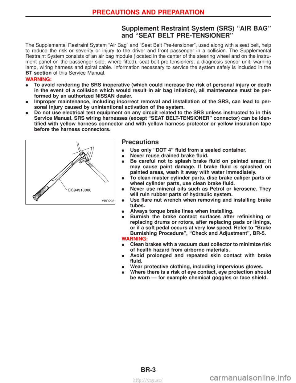
I Use flare nut wrench when removing and installing brake
tubes.
I Always torque brake lines when installing.
I Burnish the brake contact surfaces after refinishing or
replacing drums or rotors, after replacing pads or linings,
or if a soft pedal occurs at very low speed. Refer to ªBrake
Burnishing Procedureº, ªCheck and Adjustmentº, BR-5.
WARNING:
I Clean brakes with a vacuum dust collector to minimize risk
of health hazard from airborne materials.
I Avoid prolonged and repeated skin contact with brake
fluid.
I Wear protective clothing, including impervious gloves.
I Where there is a risk of eye contact, eye protection should
be worn Ð for example chemical goggles or face shield.
YBR293
PRECAUTIONS AND PREPARATION
BR-3
http://vnx.su/
Page 1171 of 1833
Preparation
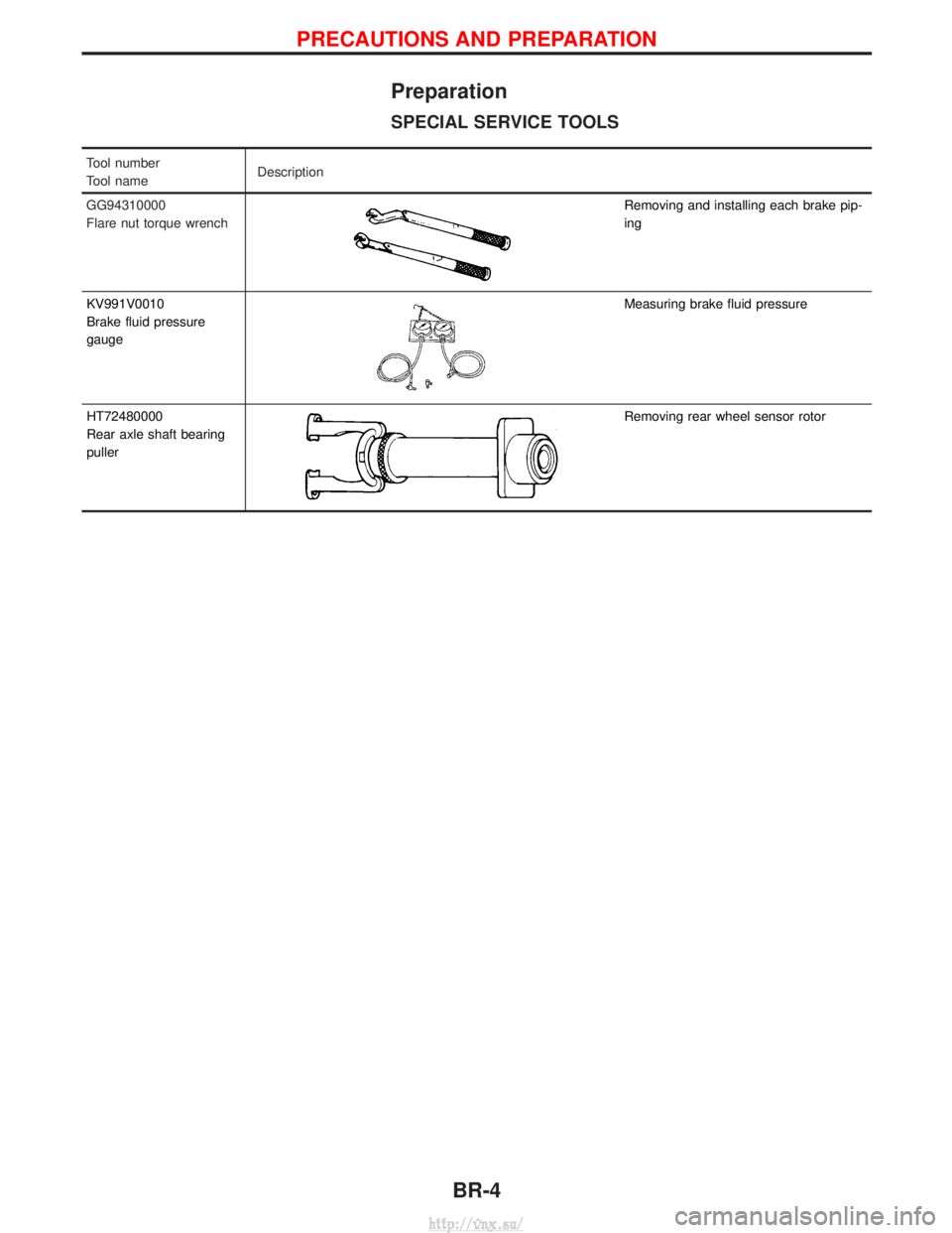
SPECIAL SERVICE TOOLS
Tool number
Tool nameDescription
GG94310000
Flare nut torque wrench
Removing and installing each brake pip-
ing
KV991V0010
Brake fluid pressure
gauge
Measuring brake fluid pressure
HT72480000
Rear axle shaft bearing
puller
Removing rear wheel sensor rotor
PRECAUTIONS AND PREPARATION
BR-4
http://vnx.su/
Page 1172 of 1833
Checking Brake Fluid Level
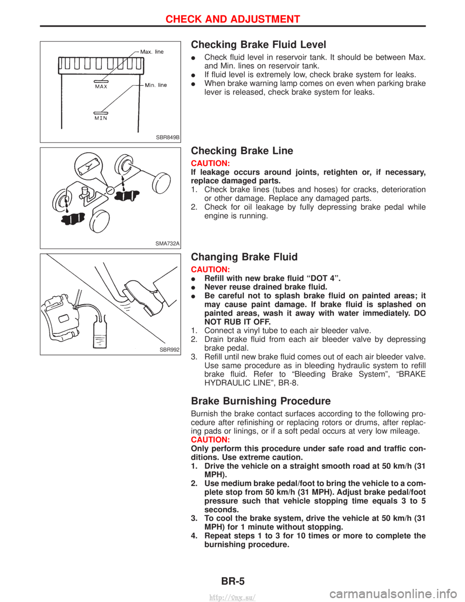
ICheck fluid level in reservoir tank. It should be between Max.
and Min. lines on reservoir tank.
I If fluid level is extremely low, check brake system for leaks.
I When brake warning lamp comes on even when parking brake
lever is released, check brake system for leaks.
Checking Brake Line
CAUTION:
If leakage occurs around joints, retighten or, if necessary,
replace damaged parts.
1. Check brake lines (tubes and hoses) for cracks, deterioration
or other damage. Replace any damaged parts.
2. Check for oil leakage by fully depressing brake pedal while engine is running.
Changing Brake Fluid
CAUTION:
IRefill with new brake fluid ªDOT 4º.
I Never reuse drained brake fluid.
I Be careful not to splash brake fluid on painted areas; it
may cause paint damage. If brake fluid is splashed on
painted areas, wash it away with water immediately. DO
NOT RUB IT OFF.
1. Connect a vinyl tube to each air bleeder valve.
2. Drain brake fluid from each air bleeder valve by depressing brake pedal.
3. Refill until new brake fluid comes out of each air bleeder valve. Use same procedure as in bleeding hydraulic system to refill
brake fluid. Refer to ªBleeding Brake Systemº, ªBRAKE
HYDRAULIC LINEº, BR-8.
Brake Burnishing Procedure
Burnish the brake contact surfaces according to the following pro-
cedure after refinishing or replacing rotors or drums, after replac-
ing pads or linings, or if a soft pedal occurs at very low mileage.
CAUTION:
Only perform this procedure under safe road and traffic con-
ditions. Use extreme caution.
1. Drive the vehicle on a straight smooth road at 50 km/h (31MPH).
2. Use medium brake pedal/foot to bring the vehicle to a com- plete stop from 50 km/h (31 MPH). Adjust brake pedal/foot
pressure such that vehicle stopping time equals 3 to 5
seconds.
3. To cool the brake system, drive the vehicle at 50 km/h (31 MPH) for 1 minute without stopping.
4. Repeat steps 1 to 3 for 10 times or more to complete the burnishing procedure.
SBR849B
SMA732A
SBR992
CHECK AND ADJUSTMENT
BR-5
http://vnx.su/
Page 1175 of 1833
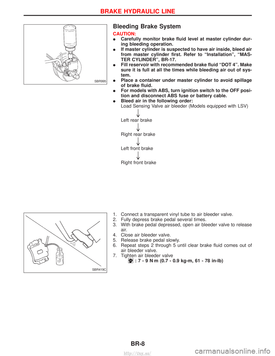
Bleeding Brake System
CAUTION:
ICarefully monitor brake fluid level at master cylinder dur-
ing bleeding operation.
I If master cylinder is suspected to have air inside, bleed air
from master cylinder first. Refer to ªInstallationº, ªMAS-
TER CYLINDERº, BR-17.
I Fill reservoir with recommended brake fluid ªDOT 4º. Make
sure it is full at all the times while bleeding air out of sys-
tem.
I Place a container under master cylinder to avoid spillage
of brake fluid.
I For models with ABS, turn ignition switch to the OFF posi-
tion and disconnect ABS fuse or battery cable.
I Bleed air in the following order:
Load Sensing Valve air bleeder (Models equipped with LSV)
"
Left rear brake
"
Right rear brake
"
Left front brake
"
Right front brake
1. Connect a transparent vinyl tube to air bleeder valve.
2. Fully depress brake pedal several times.
3. With brake pedal depressed, open air bleeder valve to release air.
4. Close air bleeder valve.
5. Release brake pedal slowly.
6. Repeat steps 2 through 5 until clear brake fluid comes out of air bleeder valve.
7. Tighten air bleeder valve
:7-9N ×m (0.7 - 0.9 kg-m, 61 - 78 in-lb)
SBR995
SBR419C
BRAKE HYDRAULIC LINE
BR-8
http://vnx.su/
Page 1176 of 1833
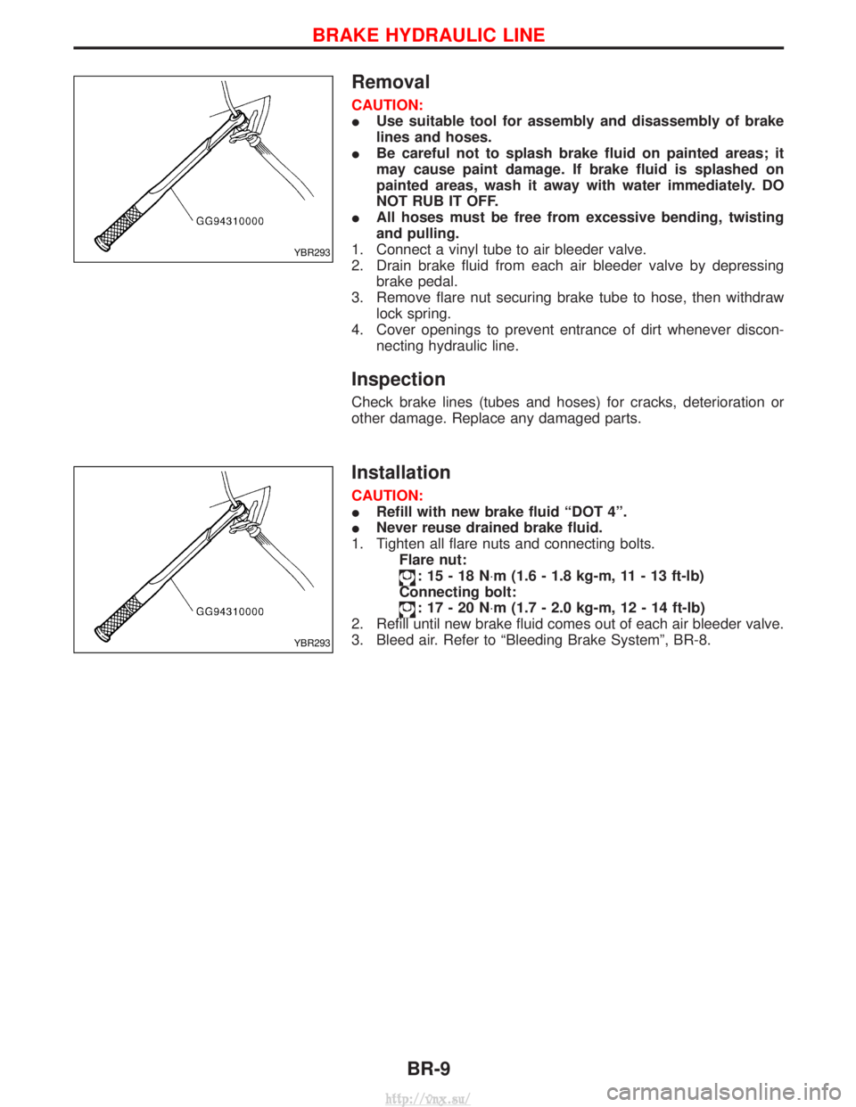
Removal
CAUTION:
IUse suitable tool for assembly and disassembly of brake
lines and hoses.
I Be careful not to splash brake fluid on painted areas; it
may cause paint damage. If brake fluid is splashed on
painted areas, wash it away with water immediately. DO
NOT RUB IT OFF.
I All hoses must be free from excessive bending, twisting
and pulling.
1. Connect a vinyl tube to air bleeder valve.
2. Drain brake fluid from each air bleeder valve by depressing brake pedal.
3. Remove flare nut securing brake tube to hose, then withdraw lock spring.
4. Cover openings to prevent entrance of dirt whenever discon- necting hydraulic line.
Inspection
Check brake lines (tubes and hoses) for cracks, deterioration or
other damage. Replace any damaged parts.
Installation
CAUTION:
IRefill with new brake fluid ªDOT 4º.
I Never reuse drained brake fluid.
1. Tighten all flare nuts and connecting bolts. Flare nut:
:15-18N ×m (1.6 - 1.8 kg-m, 11 - 13 ft-lb)
Connecting bolt:
:17-20N ×m (1.7 - 2.0 kg-m, 12 - 14 ft-lb)
2. Refill until new brake fluid comes out of each air bleeder valve.
3. Bleed air. Refer to ªBleeding Brake Systemº, BR-8.
YBR293
YBR293
BRAKE HYDRAULIC LINE
BR-9
http://vnx.su/
Page 1178 of 1833
Removal
CAUTION:
IBe careful not to splash brake fluid on painted areas; it
may cause paint damage. If brake fluid is splashed on
painted areas, wash it away with water immediately. DO
NOT RUB IT OFF.
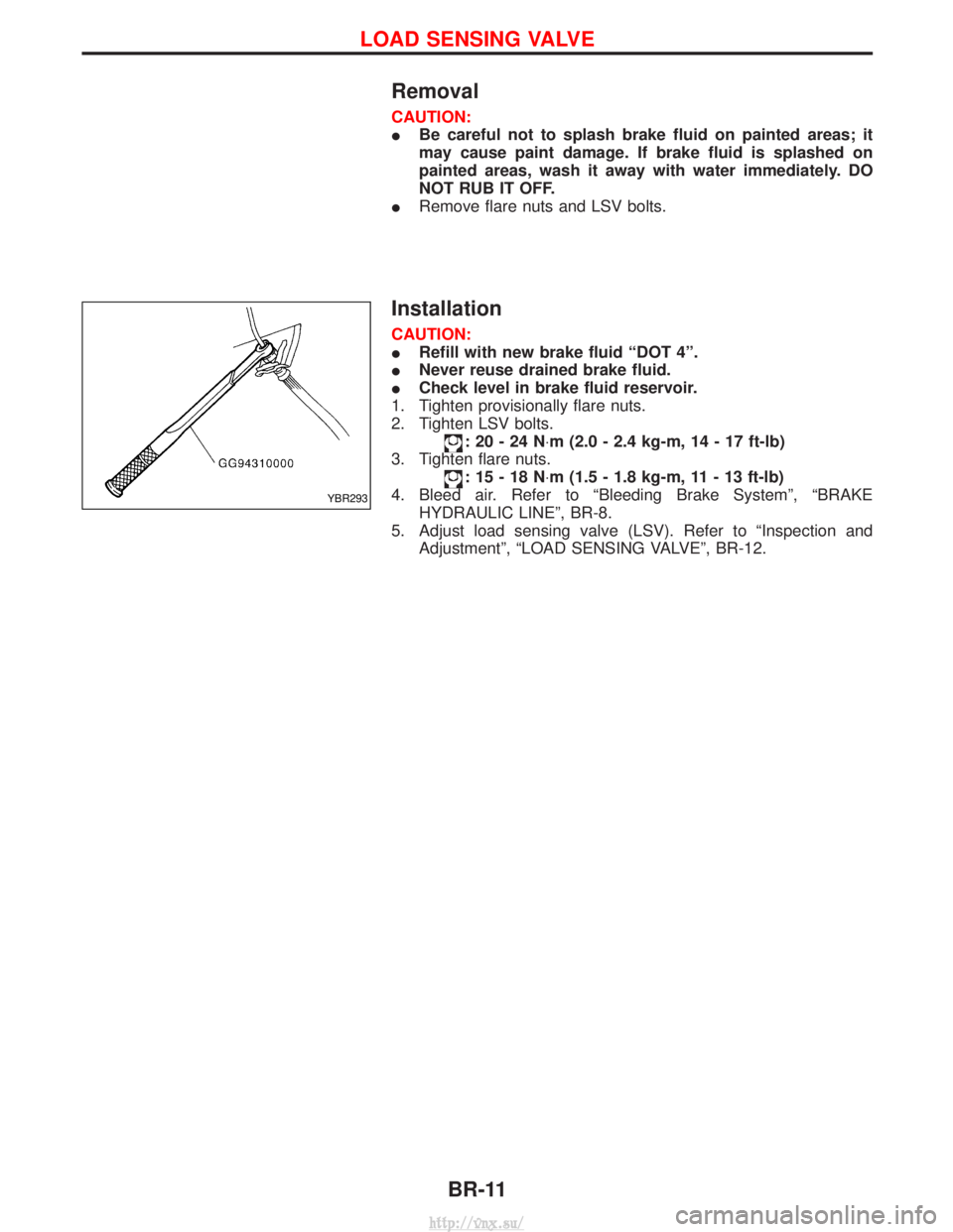
I Remove flare nuts and LSV bolts.
Installation
CAUTION:
IRefill with new brake fluid ªDOT 4º.
I Never reuse drained brake fluid.
I Check level in brake fluid reservoir.
1. Tighten provisionally flare nuts.
2. Tighten LSV bolts.
:20-24N ×m (2.0 - 2.4 kg-m, 14 - 17 ft-lb)
3. Tighten flare nuts.
:15-18N ×m (1.5 - 1.8 kg-m, 11 - 13 ft-lb)
4. Bleed air. Refer to ªBleeding Brake Systemº, ªBRAKE HYDRAULIC LINEº, BR-8.
5. Adjust load sensing valve (LSV). Refer to ªInspection and Adjustmentº, ªLOAD SENSING VALVEº, BR-12.
YBR293
LOAD SENSING VALVE
BR-11
http://vnx.su/
Page 1179 of 1833
Inspection and Adjustment
CAUTION:
ICheck level in brake fluid reservoir.
I Refill with recommended brake fluid ªDOT 4º.
I Never reuse drained brake fluid.
I Be careful not to splash brake fluid on painted areas; it
may cause paint damage. If brake fluid is splashed on
painted areas wash it away with water immediately. DO
NOT RUB IT OFF.
1. Before adjusting load sensing valve spring length, check for proper installation and abnormal wear of brake pads and
shoes.
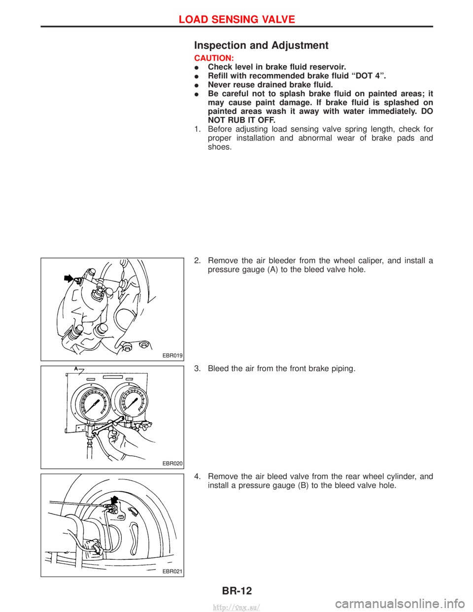
2. Remove the air bleeder from the wheel caliper, and install a pressure gauge (A) to the bleed valve hole.
3. Bleed the air from the front brake piping.
4. Remove the air bleed valve from the rear wheel cylinder, and install a pressure gauge (B) to the bleed valve hole.
EBR019
EBR020
EBR021
LOAD SENSING VALVE
BR-12
http://vnx.su/