2004 NISSAN TERRANO brake fluid
[x] Cancel search: brake fluidPage 56 of 1833
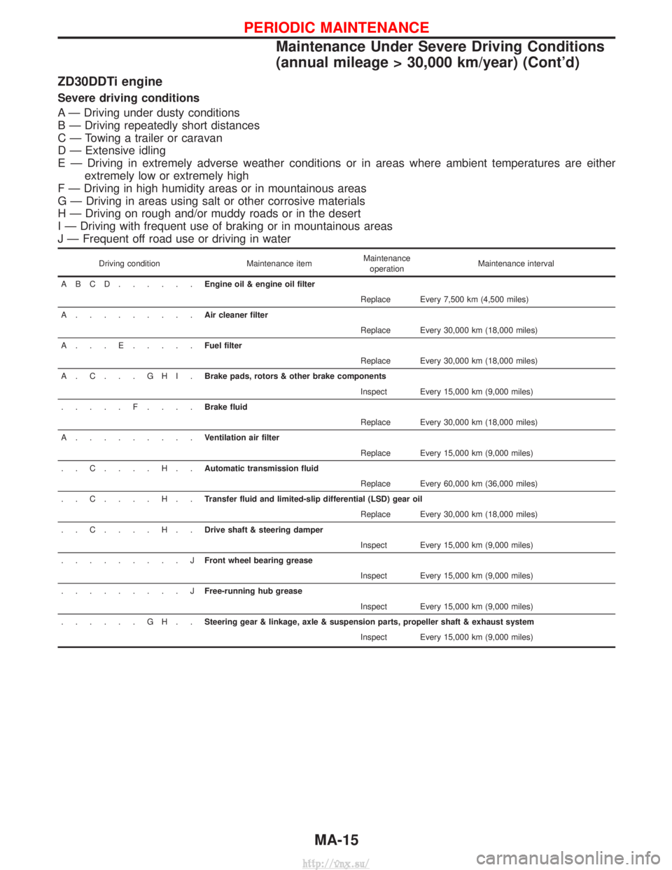
ZD30DDTi engine
Severe driving conditions
A Ð Driving under dusty conditions
B Ð Driving repeatedly short distances
C Ð Towing a trailer or caravan
D Ð Extensive idling
E Ð Driving in extremely adverse weather conditions or in areas where ambient temperatures are eitherextremely low or extremely high
F Ð Driving in high humidity areas or in mountainous areas
G Ð Driving in areas using salt or other corrosive materials
H Ð Driving on rough and/or muddy roads or in the desert
I Ð Driving with frequent use of braking or in mountainous areas
J Ð Frequent off road use or driving in water
Driving condition Maintenance itemMaintenance
operation Maintenance interval
ABCD......Engine oil & engine oil filter Replace Every 7,500 km (4,500 miles)
A.........Air cleaner filter Replace Every 30,000 km (18,000 miles)
A...E.....Fuel filter Replace Every 30,000 km (18,000 miles)
A.C...GHI.Brake pads, rotors & other brake components Inspect Every 15,000 km (9,000 miles)
.....F....Brake fluid Replace Every 30,000 km (18,000 miles)
A.........Ventilation air filter Replace Every 15,000 km (9,000 miles)
..C....H..Automatic transmission fluid Replace Every 60,000 km (36,000 miles)
..C....H..Transfer fluid and limited-slip differential (LSD) gear oil Replace Every 30,000 km (18,000 miles)
..C....H..Drive shaft & steering damper Inspect Every 15,000 km (9,000 miles)
.........J Front wheel bearing grease
Inspect Every 15,000 km (9,000 miles)
.........J Free-running hub grease
Inspect Every 15,000 km (9,000 miles)
......GH..Steering gear & linkage, axle & suspension parts, propeller shaft & exhaust system Inspect Every 15,000 km (9,000 miles)
PERIODIC MAINTENANCE
Maintenance Under Severe Driving Conditions
(annual mileage > 30,000 km/year) (Cont'd)
MA-15
http://vnx.su/
Page 58 of 1833
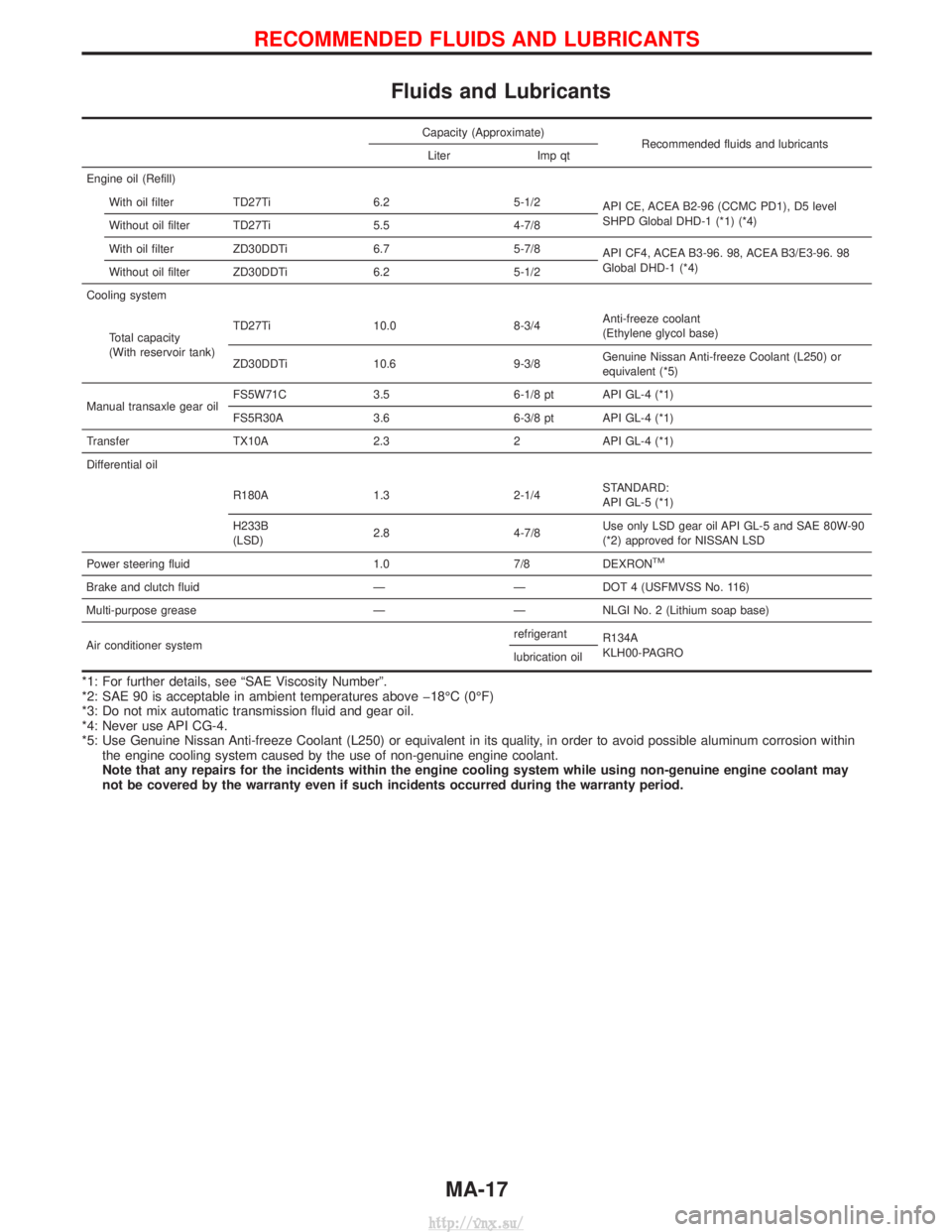
Fluids and Lubricants
Capacity (Approximate)Recommended fluids and lubricants
Liter Imp qt
Engine oil (Refill) With oil filter TD27Ti 6.2 5-1/2 API CE, ACEA B2-96 (CCMC PD1), D5 level
SHPD Global DHD-1 (*1) (*4)
Without oil filter TD27Ti 5.5 4-7/8
With oil filter ZD30DDTi 6.7 5-7/8 API CF4, ACEA B3-96. 98, ACEA B3/E3-96. 98
Global DHD-1 (*4)
Without oil filter ZD30DDTi 6.2 5-1/2
Cooling system
Total capacity
(With reservoir tank) TD27Ti 10.0 8-3/4
Anti-freeze coolant
(Ethylene glycol base)
ZD30DDTi 10.6 9-3/8 Genuine Nissan Anti-freeze Coolant (L250) or
equivalent (*5)
Manual transaxle gear oil FS5W71C 3.5 6-1/8 pt API GL-4 (*1)
FS5R30A 3.6 6-3/8 pt API GL-4 (*1)
Transfer TX10A 2.3 2 API GL-4 (*1)
Differential oil
R180A 1.3 2-1/4 STANDARD:
API GL-5 (*1)
H233B
(LSD) 2.8 4-7/8 Use only LSD gear oil API GL-5 and SAE 80W-90
(*2) approved for NISSAN LSD
Power steering fluid 1.0 7/8 DEXRON
TM
Brake and clutch fluid ÐÐDOT 4 (USFMVSS No. 116)
Multi-purpose grease Ð Ð NLGI No. 2 (Lithium soap base)
Air conditioner system refrigerant
R134A
KLH00-PAGRO
lubrication oil
*1: For further details, see ªSAE Viscosity Numberº.
*2: SAE 90 is acceptable in ambient temperatures above þ18ÉC (0ÉF)
*3: Do not mix automatic transmission fluid and gear oil.
*4: Never use API CG-4.
*5: Use Genuine Nissan Anti-freeze Coolant (L250) or equivalent in its quality, in order to avoid possible aluminum corrosion within
the engine cooling system caused by the use of non-genuine engine coolant.
Note that any repairs for the incidents within the engine cooling system while using non-genuine engine coolant may
not be covered by the warranty even if such incidents occurred during the warranty period.
RECOMMENDED FLUIDS AND LUBRICANTS
MA-17
http://vnx.su/
Page 81 of 1833
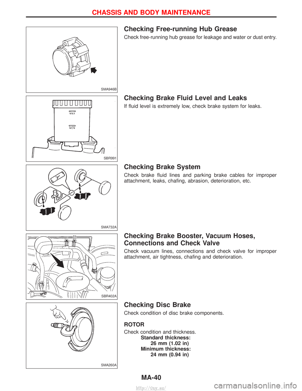
Checking Free-running Hub Grease
Check free-running hub grease for leakage and water or dust entry.
Checking Brake Fluid Level and Leaks
If fluid level is extremely low, check brake system for leaks.
Checking Brake System
Check brake fluid lines and parking brake cables for improper
attachment, leaks, chafing, abrasion, deterioration, etc.
Checking Brake Booster, Vacuum Hoses,
Connections and Check Valve
Check vacuum lines, connections and check valve for improper
attachment, air tightness, chafing and deterioration.
Checking Disc Brake
Check condition of disc brake components.
ROTOR
Check condition and thickness.Standard thickness:26 mm (1.02 in)
Minimum thickness: 24 mm (0.94 in)
SMA946B
SBR991
SMA732A
SBR402A
SMA260A
CHASSIS AND BODY MAINTENANCE
MA-40
http://vnx.su/
Page 84 of 1833

Changing Brake Fluid
1. Drain brake fluid from each air bleeder valve.
2. Refill until new brake fluid comes out from each air bleedervalve. Use same procedure as in bleeding hydraulic system to
refill brake fluid.
Refer to section BR.
I Refill with recommended brake fluid ªDOT 4º.
I Never reuse drained brake fluid.
I Be careful not to splash brake fluid on painted areas.
Balancing Wheels
Adjust wheel balance using the road wheel center.
Radial runout limit:Steel wheel:0.5 mm (0.020 in)
Aluminum wheel: 0.3 mm (0.012 in)
Lateral runout limit: Steel wheel:0.8 mm (0.031 in)
Aluminum wheel: 0.3 mm (0.012 in)
Tire Rotation
Wheel nuts
: 118 - 147 N ×m (12 - 15 kg-m, 87 - 108 ft-lb)
Checking Steering Gear and Linkage
STEERING GEAR
ICheck gear housing and boots for looseness, damage or
grease leakage.
I Check connection with steering column for looseness.
STEERING LINKAGE
ICheck ball joint, dust cover and other component parts for
looseness, wear damage or grease leakage.
SBR992
EMA039
EMA051
CHASSIS AND BODY MAINTENANCE
MA-43
http://vnx.su/
Page 765 of 1833
Precautions
IRecommended fluid is brake fluid ªDOT 4º.
I Do not reuse drained brake fluid.
I Be careful not to splash brake fluid on painted areas.
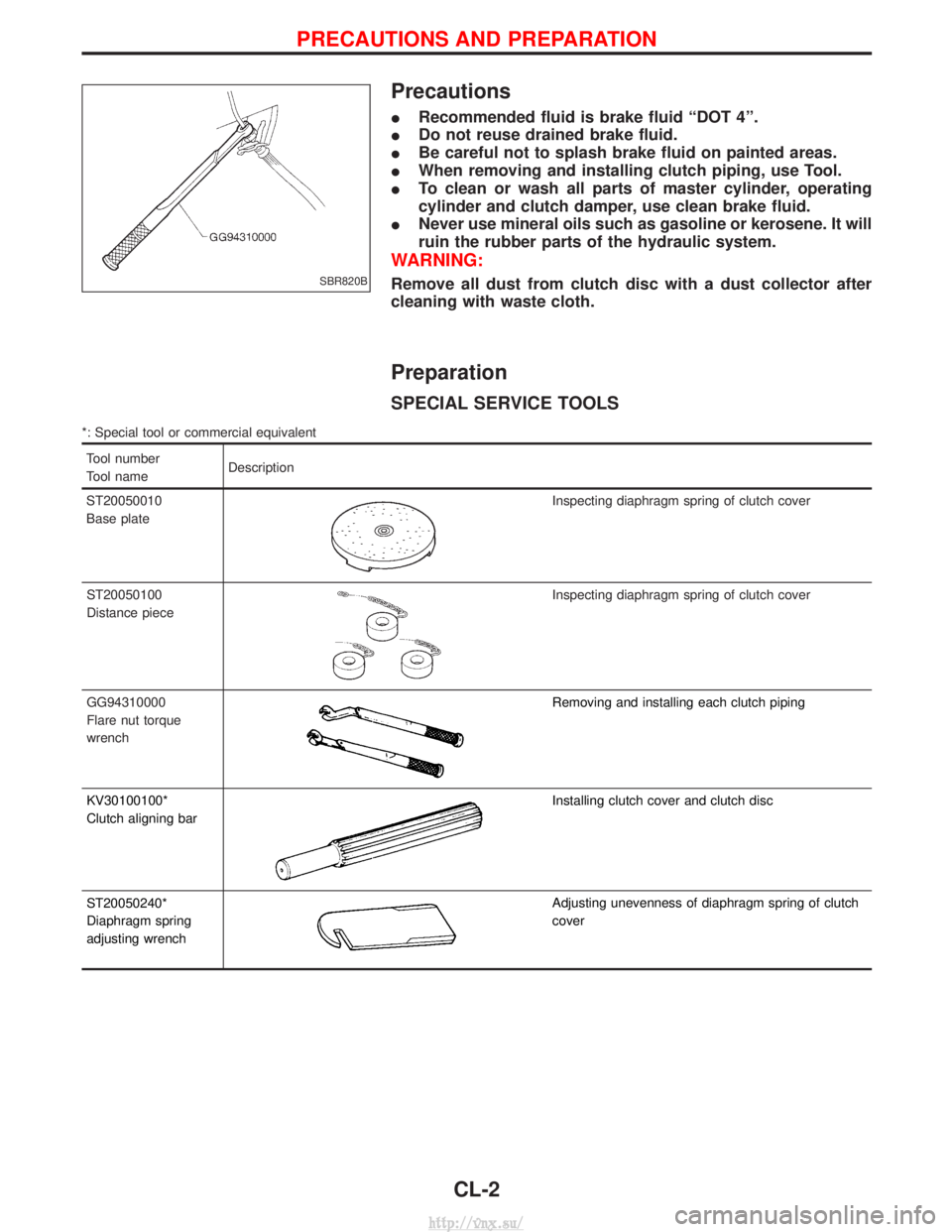
I When removing and installing clutch piping, use Tool.
I To clean or wash all parts of master cylinder, operating
cylinder and clutch damper, use clean brake fluid.
I Never use mineral oils such as gasoline or kerosene. It will
ruin the rubber parts of the hydraulic system.
WARNING:
Remove all dust from clutch disc with a dust collector after
cleaning with waste cloth.
Preparation
SPECIAL SERVICE TOOLS
*: Special tool or commercial equivalent
Tool number
Tool name Description
ST20050010
Base plate
Inspecting diaphragm spring of clutch cover
ST20050100
Distance piece
Inspecting diaphragm spring of clutch cover
GG94310000
Flare nut torque
wrench
Removing and installing each clutch piping
KV30100100*
Clutch aligning bar
Installing clutch cover and clutch disc
ST20050240*
Diaphragm spring
adjusting wrench
Adjusting unevenness of diaphragm spring of clutch
cover
SBR820B
PRECAUTIONS AND PREPARATION
CL-2
http://vnx.su/
Page 769 of 1833
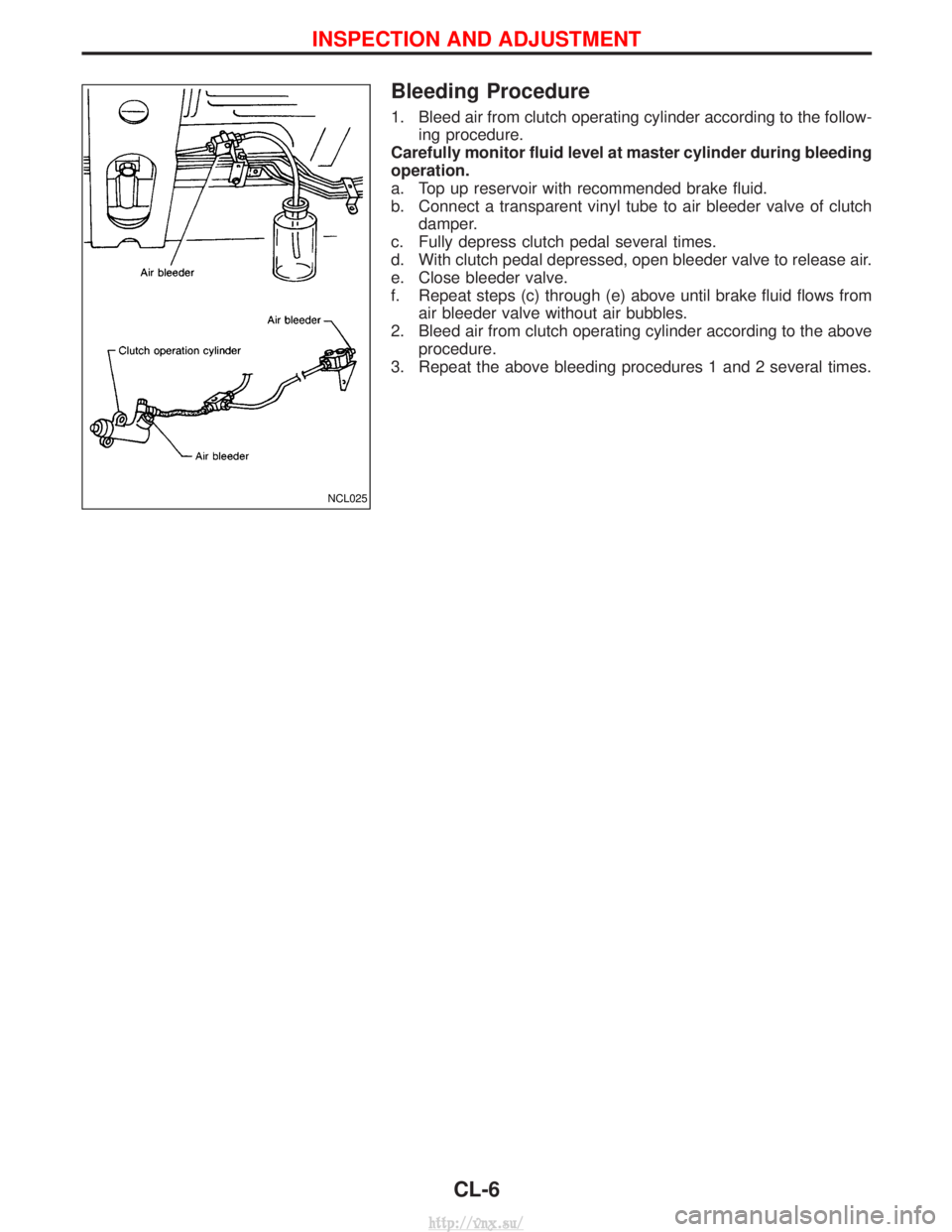
Bleeding Procedure
1. Bleed air from clutch operating cylinder according to the follow-ing procedure.
Carefully monitor fluid level at master cylinder during bleeding
operation.
a. Top up reservoir with recommended brake fluid.
b. Connect a transparent vinyl tube to air bleeder valve of clutch damper.
c. Fully depress clutch pedal several times.
d. With clutch pedal depressed, open bleeder valve to release air.
e. Close bleeder valve.
f. Repeat steps (c) through (e) above until brake fluid flows from air bleeder valve without air bubbles.
2. Bleed air from clutch operating cylinder according to the above procedure.
3. Repeat the above bleeding procedures 1 and 2 several times.
NCL025
INSPECTION AND ADJUSTMENT
CL-6
http://vnx.su/
Page 815 of 1833
Park/neutral Position, Overdrive Control or
Throttle (Accelerator) Position Switches ...................93
DIAGNOSTIC PROCEDURES FOR SYMPTOMS ........99
1. SPORT Indicator Lamp Does Not Come On ........99
2. SPORT or SNOW Indicator Lamp Does Not Come On.................................................................100
3. O/D OFF Indicator Lamp Does Not Come On....100
4. SPORT Indicator Lamp Does Not Come On ......101
5. Engine Cannot Be Started In ²P² and ²N²
Position....................................................................102
6. In ²P² Position, Vehicle Moves Forward Or
Backward When Pushed.........................................102
7. In ²N² Position, Vehicle Moves ...........................103
8. Large Shock. ²N² ->²R² Position .......................104
9. Vehicle Does Not Creep Backward In ²R²
Position....................................................................105
10. Vehicle Does Not Creep Forward In ²D² ,²2²
Or ²1² Position.........................................................106
11. Vehicle Cannot Be Started From D
1.................107
12. A/T Does Not Shift: D
1-> D2Or Does Not
Kickdown: D
4-> D2..................................................108
13. A/T Does Not Shift: D
2-> D3............................109
14. A/T Does Not Shift: D
3-> D4............................. 110
15. A/T Does Not Perform Lock-up ......................... 111
16. A/T Does Not Hold Lock-up Condition .............. 112
17. Lock-up Is Not Released ................................... 112
18. Engine Speed Does Not Return To Idle (Light Braking D
4-> D3)..................................................... 113
19. Vehicle Does Not Start From D
1....................... 114
20. A/T Does Not Shift: D
2-> D1When
Depressing Accelerator Pedal................................. 115
21. A/T Does Not Shift: D
4-> D3, When
Overdrive Control Switch ²ON² ->²OFF² ............... 116
22. A/T Does Not Shift: D
3-> 22, When Selector
Lever ²D² ->²2² Position......................................... 116
23. A/T Does Not Shift: 2
2-> 11, When Selector
Lever ²2² ->²1² Position ......................................... 117
24. Vehicle Does Not Decelerate By Engine
Brake........................................................................\
117 ON-VEHICLE SERVICE
.............................................. 118
Control Valve Assembly and Accumulators ............. 118
Revolution Sensor Replacement ............................. 119
Rear Oil Seal Replacement ..................................... 119
Parking Components Inspection.............................. 119
Park/neutral Position Switch Adjustment ................. 119
Manual Control Linkage Adjustment........................120
REMOVAL AND INSTALLATION ................................121
Removal ...................................................................121
Installation ................................................................122
MAJOR OVERHAUL ...................................................124
Oil Channel ..............................................................126
Locations of Needle Bearings, Thrust Washers
and Snap Rings .......................................................127
DISASSEMBLY ............................................................128
Disassembly.............................................................128
REPAIR FOR COMPONENT PARTS ..........................139
Oil Pump ..................................................................139
Control Valve Assembly ...........................................143
Control Valve Upper Body .......................................149
Control Valve Lower Body .......................................154
Reverse Clutch ........................................................156
High Clutch ..............................................................160
Forward and Overrun Clutches ...............................162
Low & Reverse Brake..............................................166
Forward Clutch Drum Assembly ..............................170
Rear Internal Gear and Forward Clutch Hub ..........173
Band Servo Piston Assembly ..................................176
Parking Pawl Components ......................................180
ASSEMBLY ..................................................................182
Assembly (1) ............................................................182
Adjustment ...............................................................190
Assembly (2) ............................................................193
A/T FLUID COOLER SYSTEM ...................................200
A/T Fluid Cooler.......................................................200
SERVICE DATA AND SPECIFICATIONS (SDS) ........201
General Specifications .............................................201
Specifications and Adjustment.................................201
When you read wiring diagrams:
I Read GI section, ªHOW TO READ WIRING DIAGRAMSº.
I See EL section, ªPOWER SUPPLY ROUTINGº for power distribution circuit.
When you perform trouble diagnoses, read GI section, ªHOW TO FOLLOW FLOW CHART IN
TROUBLE DIAGNOSESº and ªHOW TO PERFORM EFFICIENT DIAGNOSIS FOR AN ELECTRI-
CAL INCIDENTº.
CONTENTS(Cont'd)
AT- 2
http://vnx.su/
Page 826 of 1833
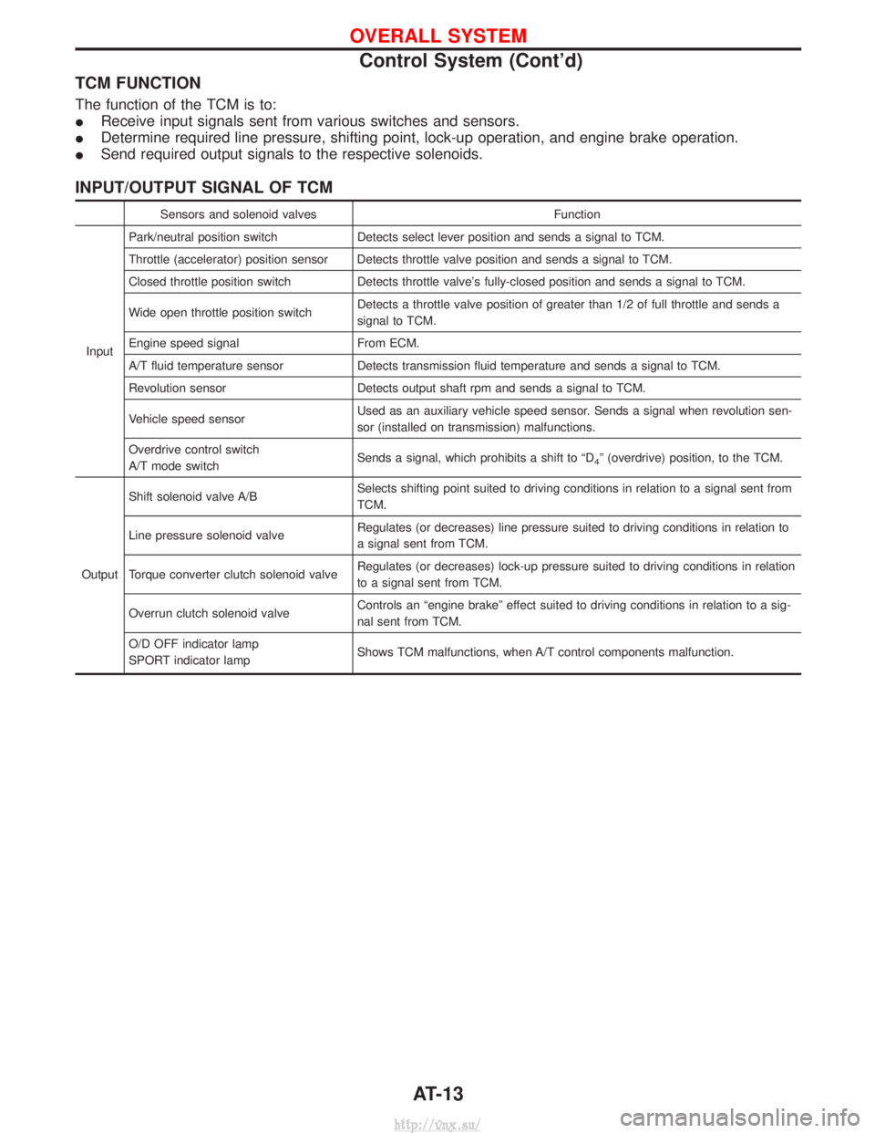
TCM FUNCTION
The function of the TCM is to:
IReceive input signals sent from various switches and sensors.
I Determine required line pressure, shifting point, lock-up operation, and engine brake operation.
I Send required output signals to the respective solenoids.
INPUT/OUTPUT SIGNAL OF TCM
Sensors and solenoid valves Function
Input Park/neutral position switch
Detects select lever position and sends a signal to TCM.
Throttle (accelerator) position sensor Detects throttle valve position and sends a signal to TCM.
Closed throttle position switch Detects throttle valve's fully-closed position and sends a signal to TCM.
Wide open throttle position switch Detects a throttle valve position of greater than 1/2 of full throttle and sends a
signal to TCM.
Engine speed signal From ECM.
A/T fluid temperature sensor Detects transmission fluid temperature and sends a signal to TCM.
Revolution sensor Detects output shaft rpm and sends a signal to TCM.
Vehicle speed sensor Used as an auxiliary vehicle speed sensor. Sends a signal when revolution sen-
sor (installed on transmission) malfunctions.
Overdrive control switch
A/T mode switch Sends a signal, which prohibits a shift to ªD
4º (overdrive) position, to the TCM.
Output Shift solenoid valve A/B
Selects shifting point suited to driving conditions in relation to a signal sent from
TCM.
Line pressure solenoid valve Regulates (or decreases) line pressure suited to driving conditions in relation to
a signal sent from TCM.
Torque converter clutch solenoid valve Regulates (or decreases) lock-up pressure suited to driving conditions in relation
to a signal sent from TCM.
Overrun clutch solenoid valve Controls an ªengine brakeº effect suited to driving conditions in relation to a sig-
nal sent from TCM.
O/D OFF indicator lamp
SPORT indicator lamp Shows TCM malfunctions, when A/T control components malfunction.
OVERALL SYSTEM
Control System (Cont'd)
AT-13
http://vnx.su/