Page 1184 of 1833

Removal
CAUTION:
Be careful not to splash brake fluid on painted areas; it may
cause paint damage. If brake fluid is splashed on painted
areas, wash it away with water immediately. DO NOT RUB.
1. Connect a vinyl tube to air bleeder valve.
2. Drain brake fluid from each air bleeder valve, depressing brakepedal to empty fluid from master cylinder.
3. Remove brake pipe flare nuts.
4. Remove master cylinder mounting nuts.
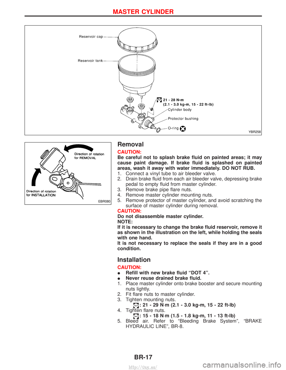
5. Remove protector of master cylinder, and avoid scratching the surface of master cylinder during removal.
CAUTION:
Do not disassemble master cylinder.
NOTE:
If it is necessary to change the brake fluid reservoir, remove it
as shown in the illustration on the left, while holding the seals
with one hand.
It is not necessary to replace the seals if they are in a good
condition.
Installation
CAUTION:
I Refill with new brake fluid ªDOT 4º.
I Never reuse drained brake fluid.
1. Place master cylinder onto brake booster and secure mounting nuts lightly.
2. Fit flare nuts to master cylinder.
3. Tighten mounting nuts.
:21-29N ×m (2.1 - 3.0 kg-m, 15 - 22 ft-lb)
4. Tighten flare nuts.
:15-18N ×m (1.5 - 1.8 kg-m, 11 - 13 ft-lb)
5. Bleed air. Refer to ªBleeding Brake Systemº, ªBRAKE HYDRAULIC LINEº, BR-8.
YBR258
EBR080
MASTER CYLINDER
BR-17
http://vnx.su/
Page 1186 of 1833

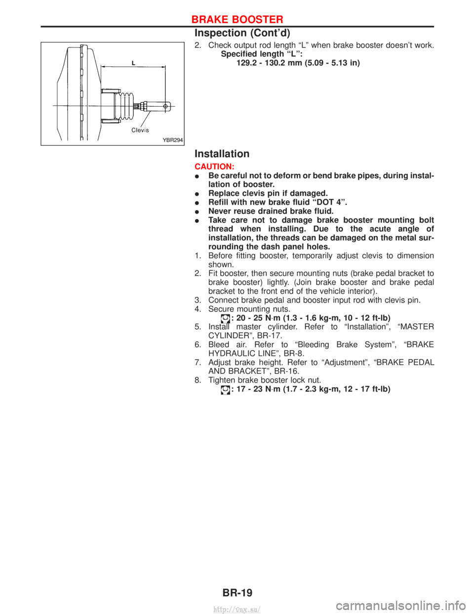
2. Check output rod length ªLº when brake booster doesn't work.Specified length ªLº:129.2 - 130.2 mm (5.09 - 5.13 in)
Installation
CAUTION:
IBe careful not to deform or bend brake pipes, during instal-
lation of booster.
I Replace clevis pin if damaged.
I Refill with new brake fluid ªDOT 4º.
I Never reuse drained brake fluid.
I Take care not to damage brake booster mounting bolt
thread when installing. Due to the acute angle of
installation, the threads can be damaged on the metal sur-
rounding the dash panel holes.
1. Before fitting booster, temporarily adjust clevis to dimension shown.
2. Fit booster, then secure mounting nuts (brake pedal bracket to brake booster) lightly. (Join brake booster and brake pedal
bracket to the front end of the vehicle interior).
3. Connect brake pedal and booster input rod with clevis pin.
4. Secure mounting nuts.
:20-25N ×m (1.3 - 1.6 kg-m, 10 - 12 ft-lb)
5. Install master cylinder. Refer to ªInstallationº, ªMASTER CYLINDERº, BR-17.
6. Bleed air. Refer to ªBleeding Brake Systemº, ªBRAKE HYDRAULIC LINEº, BR-8.
7. Adjust brake height. Refer to ªAdjustmentº, ªBRAKE PEDAL AND BRACKETº, BR-16.
8. Tighten brake booster lock nut.
:17-23N ×m (1.7 - 2.3 kg-m, 12 - 17 ft-lb)
YBR294
BRAKE BOOSTER
Inspection (Cont'd)
BR-19
http://vnx.su/
Page 1194 of 1833
PRECAUTION:
Clean all brake assembly parts with a vacuum dust collector
to prevent particles from spreading through work area.
Pad Replacement
1. Loosen brake fluid reservoir cap.
2. Remove lower pin bolt.
YBR297
SBR081A
FRONT DISC BRAKE
BR-27
http://vnx.su/
Page 1195 of 1833

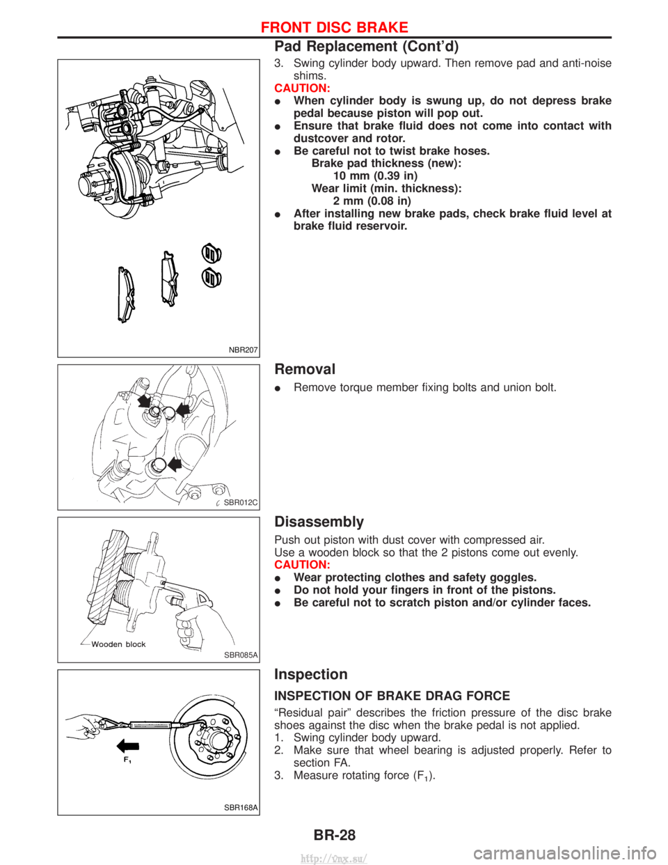
3. Swing cylinder body upward. Then remove pad and anti-noiseshims.
CAUTION:
I When cylinder body is swung up, do not depress brake
pedal because piston will pop out.
I Ensure that brake fluid does not come into contact with
dustcover and rotor.
I Be careful not to twist brake hoses.
Brake pad thickness (new): 10 mm (0.39 in)
Wear limit (min. thickness): 2 mm (0.08 in)
I After installing new brake pads, check brake fluid level at
brake fluid reservoir.
Removal
IRemove torque member fixing bolts and union bolt.
Disassembly
Push out piston with dust cover with compressed air.
Use a wooden block so that the 2 pistons come out evenly.
CAUTION:
IWear protecting clothes and safety goggles.
I Do not hold your fingers in front of the pistons.
I Be careful not to scratch piston and/or cylinder faces.
Inspection
INSPECTION OF BRAKE DRAG FORCE
ªResidual pairº describes the friction pressure of the disc brake
shoes against the disc when the brake pedal is not applied.
1. Swing cylinder body upward.
2. Make sure that wheel bearing is adjusted properly. Refer to
section FA.
3. Measure rotating force (F
1).
NBR207
SBR012C
SBR085A
SBR168A
FRONT DISC BRAKE
Pad Replacement (Cont'd)
BR-28
http://vnx.su/
Page 1196 of 1833

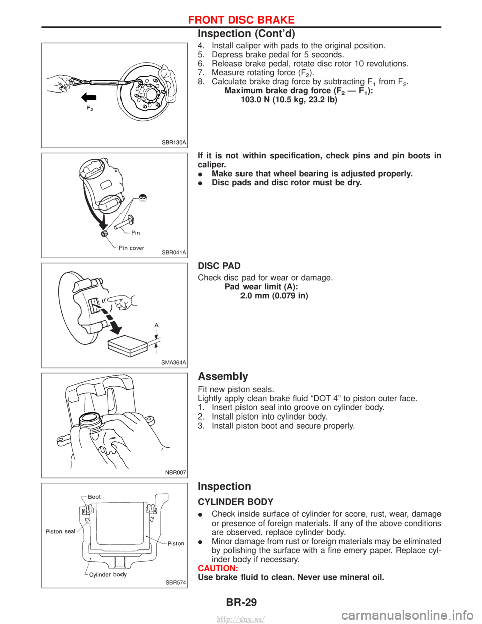
4. Install caliper with pads to the original position.
5. Depress brake pedal for 5 seconds.
6. Release brake pedal, rotate disc rotor 10 revolutions.
7. Measure rotating force (F
2).
8. Calculate brake drag force by subtracting F
1from F2.
Maximum brake drag force (F
2ÐF1):
103.0 N (10.5 kg, 23.2 lb)
If it is not within specification, check pins and pin boots in
caliper.
I Make sure that wheel bearing is adjusted properly.
I Disc pads and disc rotor must be dry.
DISC PAD
Check disc pad for wear or damage.
Pad wear limit (A):2.0 mm (0.079 in)
Assembly
Fit new piston seals.
Lightly apply clean brake fluid ªDOT 4º to piston outer face.
1. Insert piston seal into groove on cylinder body.
2. Install piston into cylinder body.
3. Install piston boot and secure properly.
Inspection
CYLINDER BODY
ICheck inside surface of cylinder for score, rust, wear, damage
or presence of foreign materials. If any of the above conditions
are observed, replace cylinder body.
I Minor damage from rust or foreign materials may be eliminated
by polishing the surface with a fine emery paper. Replace cyl-
inder body if necessary.
CAUTION:
Use brake fluid to clean. Never use mineral oil.
SBR130A
SBR041A
SMA364A
NBR007
SBR574
FRONT DISC BRAKE
Inspection (Cont'd)
BR-29
http://vnx.su/
Page 1198 of 1833
Installation
CAUTION:
IRefill with new brake fluid ªDOT 4º.
I Never reuse drained brake fluid.
1. Install caliper assembly.
2. Install brake hose to caliper securely taking care that brake hose is not trapped between any suspension part and that
hoses are not twisted.
3. Bleed air. Refer to ªBleeding Brake Systemº, ªBRAKE HYDRAULIC LINEº, BR-8.
SBR014C
FRONT DISC BRAKE
BR-31
http://vnx.su/
Page 1209 of 1833
ABS actuator operation
Inlet solenoid
valveOutlet solenoid
valve
Normal brake operation OFF (Open) OFF (Closed) Master cylinder brake fluid pressure is directly trans-
mitted to caliper via the inlet solenoid valve.
ABS operation Pressure hold ON (Closed) OFF (Closed)
Hydraulic circuit is shut off to hold the caliper brake
fluid pressure.
Pressure
decrease ON (Closed) ON (Open) Caliper brake fluid is sent to reservoir via the outlet
solenoid valve. Then it is pushed up to the master
cylinder by pump.
Pressure
increase OFF (Open) OFF (Closed) Master cylinder brake fluid pressure is transmitted to
caliper.
ANTI-LOCK BRAKE SYSTEM
System Description (Cont'd)
BR-42
http://vnx.su/
Page 1213 of 1833
ACTUATOR
Removal
1. Disconnect battery cable.
2. Drain brake fluid. Refer to BR-5.
3. Unlock the slider then disconnect the electrical harness con-nectors from ABS control unit.
4. Identify each brake pipe with corresponding actuator port hole and mark them accordingly.
5. Disconnect brake pipes and move them away from actuator. Do not force brake pipes so as to kink them or bend them exces-
sively.
Ensure that brake fluid does not come into contact with
any parts.
YBR299
ANTI-LOCK BRAKE SYSTEM
Removal and Installation (Cont'd)
BR-46
http://vnx.su/