Page 1214 of 1833
6. Loosen/remove mounting nuts between actuator and bracket.
Installation
CAUTION:
After installation, pay attention to the following points:
IRefill brake fluid and bleed air. Refer to ªCHECK AND
ADJUSTMENTº, BR-5 and ªBleeding Brake Systemº,
ªBRAKE HYDRAULIC LINEº, BR-8, respectively.
1. Install actuator on bracket without tightening fixings.
2. Assemble brake tubes to actuator without tightening tube nuts. Ensure that correct tubes are connected to each port.
3. Fully tighten actuator and bracket fixings to specified torque.
4. Fully tighten flare nuts to specified torque, BR-9.
5. Secure ABS control unit harness connector and battery cable.
ANTI-LOCK BRAKE SYSTEM
Removal and Installation (Cont'd)
BR-47
http://vnx.su/
Page 1215 of 1833
How to Perform Trouble Diagnoses for Quick
and Accurate Repair
INTRODUCTION
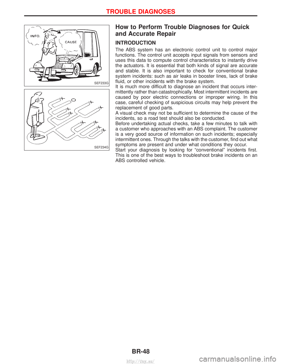
The ABS system has an electronic control unit to control major
functions. The control unit accepts input signals from sensors and
uses this data to compute control characteristics to instantly drive
the actuators. It is essential that both kinds of signal are accurate
and stable. It is also important to check for conventional brake
system incidents: such as air leaks in booster lines, lack of brake
fluid, or other incidents with the brake system.
It is much more difficult to diagnose an incident that occurs inter-
mittently rather than catastrophically. Most intermittent incidents are
caused by poor electric connections or improper wiring. In this
case, careful checking of suspicious circuits may help prevent the
replacement of good parts.
A visual check may not be sufficient to determine the cause of the
incidents, so a road test should also be conducted.
Before undertaking actual checks, take a few minutes to talk with
a customer who approaches with an ABS complaint. The customer
is a very good source of information on such incidents; especially
intermittent ones. Through the talks with the customer, find out what
symptoms are present and under what conditions they occur.
Start your diagnosis by looking for ªconventionalº incidents first.
This is one of the best ways to troubleshoot brake incidents on an
ABS controlled vehicle.
SEF233G
SEF234G
TROUBLE DIAGNOSES
BR-48
http://vnx.su/
Page 1232 of 1833
ACTIVE TEST MODE
TEST ITEMCONDITION JUDGEMENT
FR RH SOLENOID
FR LH SOLENOID
RR SOLENOID Engine is running.Brake fluid pressure control operation
IN SOL OUT SOL
UP (Increase):
KEEP (Hold):
DOWN (Decrease): OFF
ON
ON OFF
OFF
ON
ABS MOTOR ABS actuator motor
ON: Motor runs (ABS motor relay ON)
OFF: Motor stops (ABS motor relay OFF)
G-SWITCH Ignition switch is ON or
engine is running.Check G-switch circuit
OFF: G-switch OFF
ON: G-switch ON
Note: Active test will automatically stop ten seconds after the test starts. (LIMIT SIGNAL monitor shows
ON.)
TROUBLE DIAGNOSES
CONSULT-II Inspection Procedure (Cont'd)
BR-65
http://vnx.su/
Page 1233 of 1833
Preliminary Check
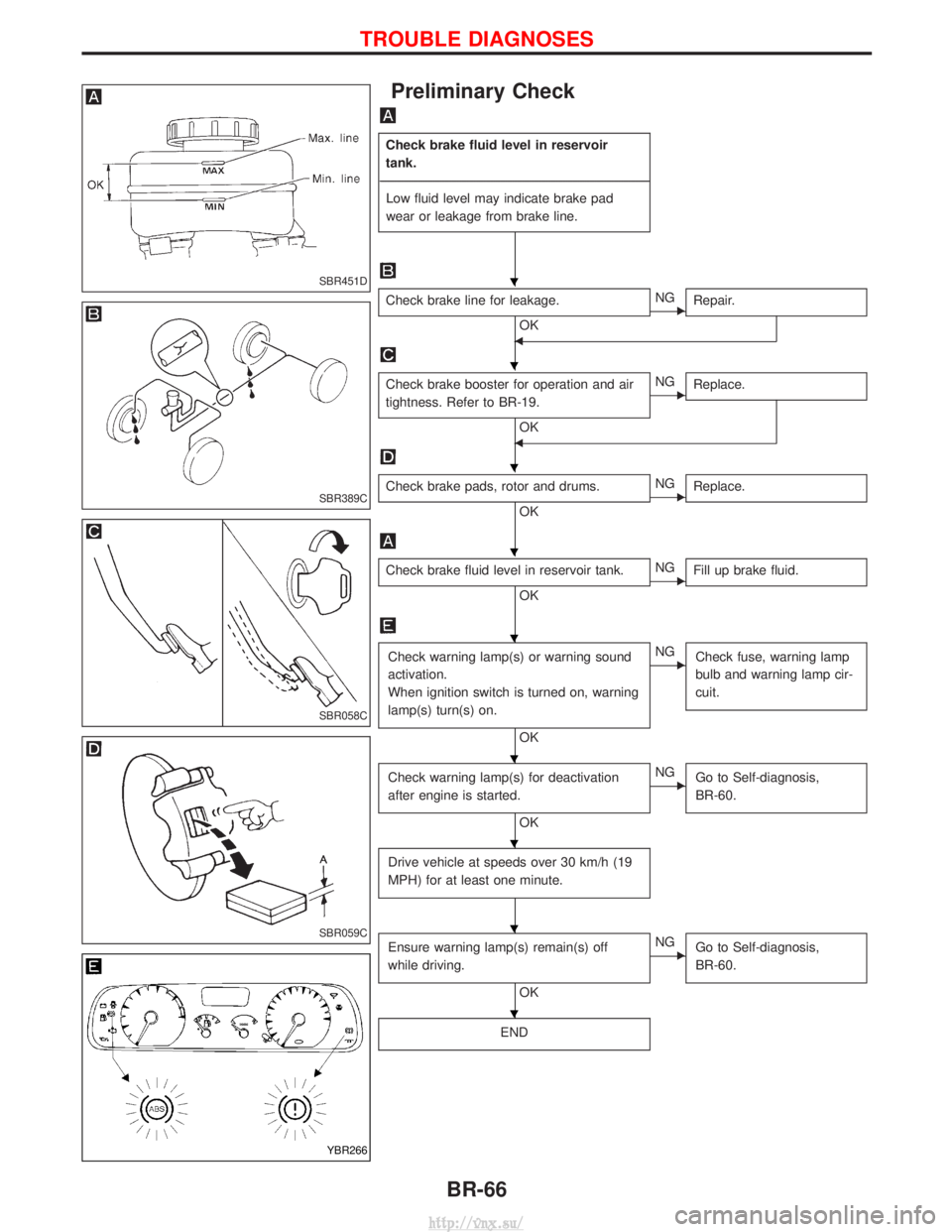
Check brake fluid level in reservoir
tank.
---------------------------------------------------------------------------------------------------------------------------------------------------------------------------------------------------------------------------------------------------------------------------------------------------------------- Low fluid level may indicate brake pad
wear or leakage from brake line.
Check brake line for leakage.
OKENG Repair.
F
Check brake booster for operation and air
tightness. Refer to BR-19.
OK
ENGReplace.
F
Check brake pads, rotor and drums.
OKENGReplace.
Check brake fluid level in reservoir tank.
OKENGFill up brake fluid.
Check warning lamp(s) or warning sound
activation.
When ignition switch is turned on, warning
lamp(s) turn(s) on.
OK
ENG
Check fuse, warning lamp
bulb and warning lamp cir-
cuit.
Check warning lamp(s) for deactivation
after engine is started.
OK
ENGGo to Self-diagnosis,
BR-60.
Drive vehicle at speeds over 30 km/h (19
MPH) for at least one minute.
Ensure warning lamp(s) remain(s) off
while driving.
OK
ENGGo to Self-diagnosis,
BR-60.
END
SBR451D
SBR389C
SBR058C
SBR059C
YBR266
H
H
H
H
H
H
H
H
H
TROUBLE DIAGNOSES
BR-66
http://vnx.su/
Page 1252 of 1833
General Specifications
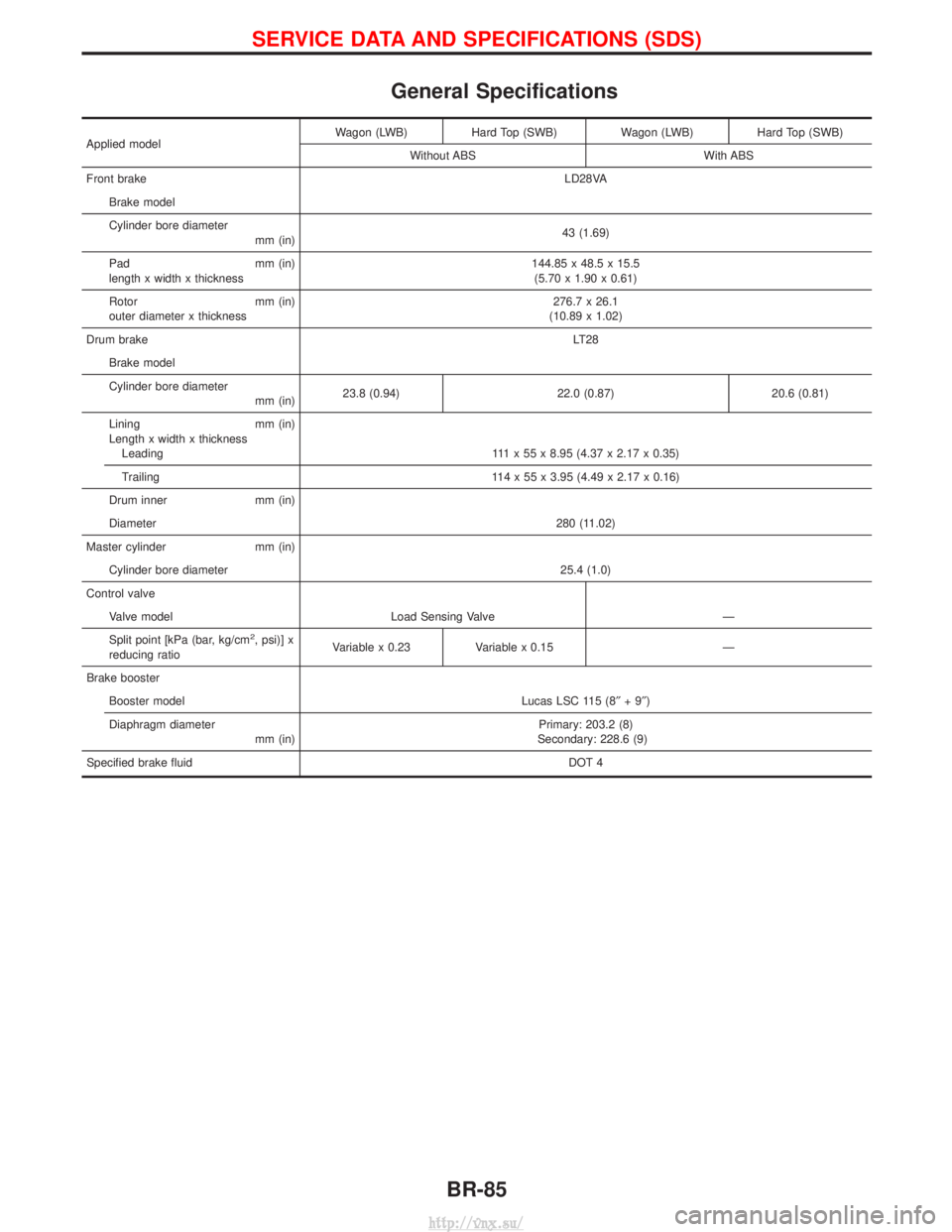
Applied modelWagon (LWB) Hard Top (SWB) Wagon (LWB) Hard Top (SWB)
Without ABS With ABS
Front brake LD28VA
Brake model
Cylinder bore diameter mm (in) 43 (1.69)
Pad mm (in)
length x width x thickness 144.85 x 48.5 x 15.5
(5.70 x 1.90 x 0.61)
Rotor mm (in)
outer diameter x thickness 276.7 x 26.1
(10.89 x 1.02)
Drum brake LT28
Brake model
Cylinder bore diameter mm (in)23.8 (0.94) 22.0 (0.87) 20.6 (0.81)
Lining mm (in)
Length x width x thickness Leading 111 x 55 x 8.95 (4.37 x 2.17 x 0.35)
Trailing 114 x 55 x 3.95 (4.49 x 2.17 x 0.16)
Drum inner mm (in)
Diameter 280 (11.02)
Master cylinder mm (in) Cylinder bore diameter 25.4 (1.0)
Control valve Valve model Load Sensing Valve Ð
Split point [kPa (bar, kg/cm
2, psi)] x
reducing ratio Variable x 0.23 Variable x 0.15 Ð
Brake booster Booster model Lucas LSC 115 (8² +9²)
Diaphragm diameter mm (in) Primary: 203.2 (8)
Secondary: 228.6 (9)
Specified brake fluid DOT 4
SERVICE DATA AND SPECIFICATIONS (SDS)
BR-85
http://vnx.su/
Page 1259 of 1833
Checking Steering Wheel Turning Force
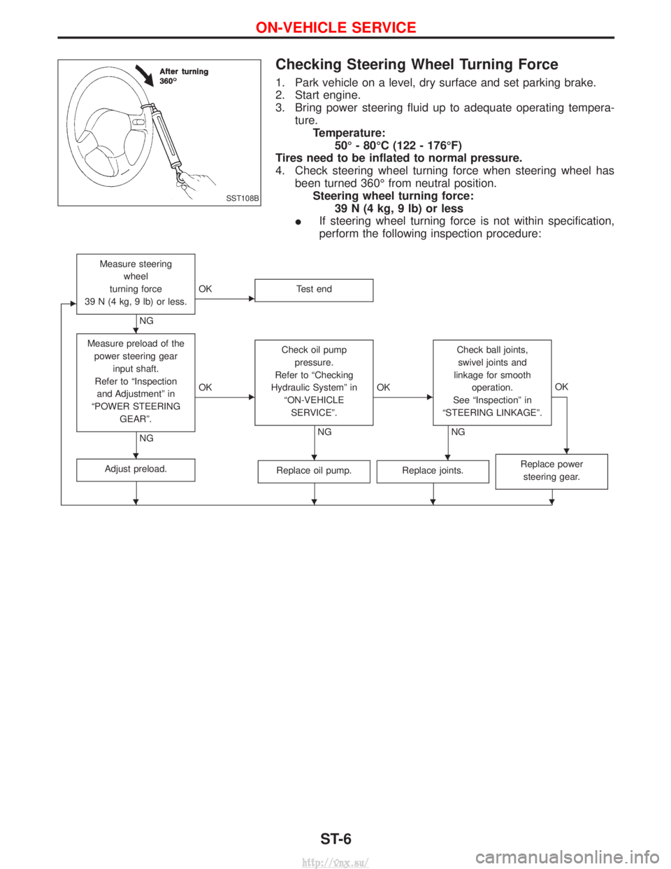
1. Park vehicle on a level, dry surface and set parking brake.
2. Start engine.
3. Bring power steering fluid up to adequate operating tempera-ture.Temperature: 50É - 80ÉC (122 - 176ÉF)
Tires need to be inflated to normal pressure.
4. Check steering wheel turning force when steering wheel has been turned 360É from neutral position.Steering wheel turning force: 39 N (4 kg, 9 lb) or less
I If steering wheel turning force is not within specification,
perform the following inspection procedure:
E
Measure steering
wheel
turning force
39 N (4 kg, 9 lb) or less.
NG
EOK Test end
Measure preload of the
power steering gear input shaft.
Refer to ªInspection and Adjustmentº in
ªPOWER STEERING GEARº.
NG
EOK Check oil pump
pressure.
Refer to ªChecking
Hydraulic Systemº in ªON-VEHICLESERVICEº.
NG
EOK Check ball joints,
swivel joints and
linkage for smooth operation.
See ªInspectionº in
ªSTEERING LINKAGEº.
NG OK
Adjust preload.Replace oil pump.Replace joints.Replace power
steering gear.
SST108B
H
HHHH
HHHH
ON-VEHICLE SERVICE
ST-6
http://vnx.su/
Page 1513 of 1833
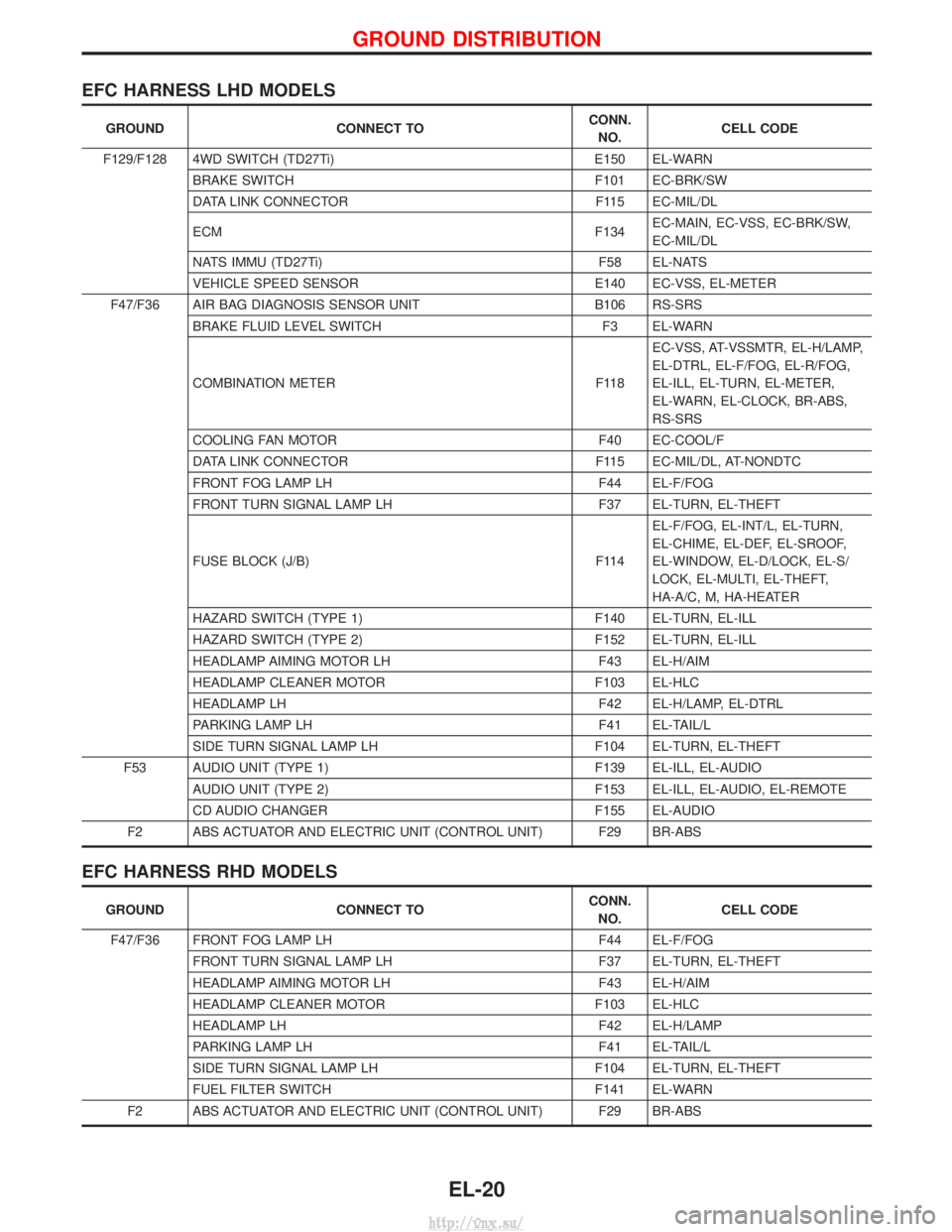
EFC HARNESS LHD MODELS
GROUNDCONNECT TO CONN.
NO. CELL CODE
F129/F128 4WD SWITCH (TD27Ti) E150 EL-WARN
BRAKE SWITCH F101 EC-BRK/SW
DATA LINK CONNECTOR F115 EC-MIL/DL
ECM F134EC-MAIN, EC-VSS, EC-BRK/SW,
EC-MIL/DL
NATS IMMU (TD27Ti) F58 EL-NATS
VEHICLE SPEED SENSOR E140 EC-VSS, EL-METER
F47/F36 AIR BAG DIAGNOSIS SENSOR UNIT B106 RS-SRS
BRAKE FLUID LEVEL SWITCH F3 EL-WARN
COMBINATION METER F118EC-VSS, AT-VSSMTR, EL-H/LAMP,
EL-DTRL, EL-F/FOG, EL-R/FOG,
EL-ILL, EL-TURN, EL-METER,
EL-WARN, EL-CLOCK, BR-ABS,
RS-SRS
COOLING FAN MOTOR F40 EC-COOL/F
DATA LINK CONNECTOR F115 EC-MIL/DL, AT-NONDTC
FRONT FOG LAMP LH F44 EL-F/FOG
FRONT TURN SIGNAL LAMP LH F37 EL-TURN, EL-THEFT
FUSE BLOCK (J/B) F114EL-F/FOG, EL-INT/L, EL-TURN,
EL-CHIME, EL-DEF, EL-SROOF,
EL-WINDOW, EL-D/LOCK, EL-S/
LOCK, EL-MULTI, EL-THEFT,
HA-A/C, M, HA-HEATER
HAZARD SWITCH (TYPE 1) F140 EL-TURN, EL-ILL
HAZARD SWITCH (TYPE 2) F152 EL-TURN, EL-ILL
HEADLAMP AIMING MOTOR LH F43 EL-H/AIM
HEADLAMP CLEANER MOTOR F103 EL-HLC
HEADLAMP LH F42 EL-H/LAMP, EL-DTRL
PARKING LAMP LH F41 EL-TAIL/L
SIDE TURN SIGNAL LAMP LH F104 EL-TURN, EL-THEFT
F53 AUDIO UNIT (TYPE 1) F139 EL-ILL, EL-AUDIO
AUDIO UNIT (TYPE 2) F153 EL-ILL, EL-AUDIO, EL-REMOTE
CD AUDIO CHANGER F155 EL-AUDIO
F2 ABS ACTUATOR AND ELECTRIC UNIT (CONTROL UNIT) F29 BR-ABS
EFC HARNESS RHD MODELS
GROUND CONNECT TO CONN.
NO. CELL CODE
F47/F36 FRONT FOG LAMP LH F44 EL-F/FOG
FRONT TURN SIGNAL LAMP LH F37 EL-TURN, EL-THEFT
HEADLAMP AIMING MOTOR LH F43 EL-H/AIM
HEADLAMP CLEANER MOTOR F103 EL-HLC
HEADLAMP LH F42 EL-H/LAMP
PARKING LAMP LH F41 EL-TAIL/L
SIDE TURN SIGNAL LAMP LH F104 EL-TURN, EL-THEFT
FUEL FILTER SWITCH F141 EL-WARN
F2 ABS ACTUATOR AND ELECTRIC UNIT (CONTROL UNIT) F29 BR-ABS
GROUND DISTRIBUTION
EL-20
http://vnx.su/
Page 1515 of 1833
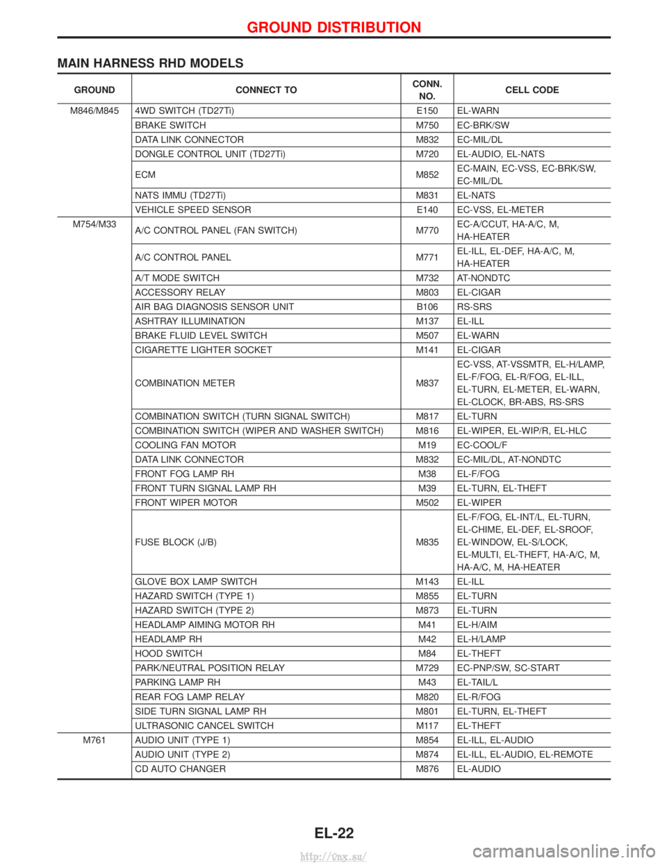
MAIN HARNESS RHD MODELS
GROUNDCONNECT TO CONN.
NO. CELL CODE
M846/M845 4WD SWITCH (TD27Ti) E150 EL-WARN
BRAKE SWITCH M750 EC-BRK/SW
DATA LINK CONNECTOR M832 EC-MIL/DL
DONGLE CONTROL UNIT (TD27Ti) M720 EL-AUDIO, EL-NATS
ECM M852EC-MAIN, EC-VSS, EC-BRK/SW,
EC-MIL/DL
NATS IMMU (TD27Ti) M831 EL-NATS
VEHICLE SPEED SENSOR E140 EC-VSS, EL-METER
M754/M33 A/C CONTROL PANEL (FAN SWITCH) M770EC-A/CCUT, HA-A/C, M,
HA-HEATER
A/C CONTROL PANEL M771EL-ILL, EL-DEF, HA-A/C, M,
HA-HEATER
A/T MODE SWITCH M732 AT-NONDTC
ACCESSORY RELAY M803 EL-CIGAR
AIR BAG DIAGNOSIS SENSOR UNIT B106 RS-SRS
ASHTRAY ILLUMINATION M137 EL-ILL
BRAKE FLUID LEVEL SWITCH M507 EL-WARN
CIGARETTE LIGHTER SOCKET M141 EL-CIGAR
COMBINATION METER M837EC-VSS, AT-VSSMTR, EL-H/LAMP,
EL-F/FOG, EL-R/FOG, EL-ILL,
EL-TURN, EL-METER, EL-WARN,
EL-CLOCK, BR-ABS, RS-SRS
COMBINATION SWITCH (TURN SIGNAL SWITCH) M817 EL-TURN
COMBINATION SWITCH (WIPER AND WASHER SWITCH) M816 EL-WIPER, EL-WIP/R, EL-HLC
COOLING FAN MOTOR M19 EC-COOL/F
DATA LINK CONNECTOR M832 EC-MIL/DL, AT-NONDTC
FRONT FOG LAMP RH M38 EL-F/FOG
FRONT TURN SIGNAL LAMP RH M39 EL-TURN, EL-THEFT
FRONT WIPER MOTOR M502 EL-WIPER
FUSE BLOCK (J/B) M835 EL-F/FOG, EL-INT/L, EL-TURN,
EL-CHIME, EL-DEF, EL-SROOF,
EL-WINDOW, EL-S/LOCK,
EL-MULTI, EL-THEFT, HA-A/C, M,
HA-A/C, M, HA-HEATER
GLOVE BOX LAMP SWITCH M143 EL-ILL
HAZARD SWITCH (TYPE 1) M855 EL-TURN
HAZARD SWITCH (TYPE 2) M873 EL-TURN
HEADLAMP AIMING MOTOR RH M41 EL-H/AIM
HEADLAMP RH M42 EL-H/LAMP
HOOD SWITCH M84 EL-THEFT
PARK/NEUTRAL POSITION RELAY M729 EC-PNP/SW, SC-START
PARKING LAMP RH M43 EL-TAIL/L
REAR FOG LAMP RELAY M820 EL-R/FOG
SIDE TURN SIGNAL LAMP RH M801 EL-TURN, EL-THEFT
ULTRASONIC CANCEL SWITCH M117 EL-THEFT
M761 AUDIO UNIT (TYPE 1) M854 EL-ILL, EL-AUDIO AUDIO UNIT (TYPE 2) M874 EL-ILL, EL-AUDIO, EL-REMOTE
CD AUTO CHANGER M876 EL-AUDIO
GROUND DISTRIBUTION
EL-22
http://vnx.su/