Page 705 of 3870
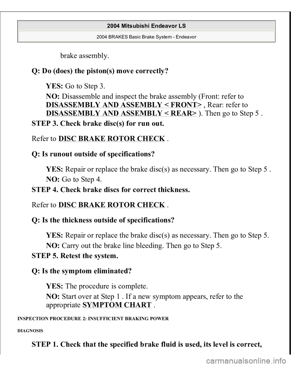
brake assembly.
Q: Do (does) the piston(s) move correctly?
YES: Go to Step 3.
NO: Disassemble and inspect the brake assembly (Front: refer to
DISASSEMBLY AND ASSEMBLY < FRONT>
, Rear: refer to
DISASSEMBLY AND ASSEMBLY < REAR> ). Then go to Step 5 .
STEP 3. Check brake disc(s) for run out.
Refer to DISC BRAKE ROTOR CHECK
.
Q: Is runout outside of specifications?
YES: Repair or replace the brake disc(s) as necessary. Then go to Step 5 .
NO: Go to Step 4.
STEP 4. Check brake discs for correct thickness.
Refer to DISC BRAKE ROTOR CHECK .
Q: Is the thickness outside of specifications?
YES: Repair or replace the brake disc(s) as necessary. Then go to Step 5.
NO: Carry out the brake line bleeding. Then go to Step 5.
STEP 5. Retest the system.
Q: Is the symptom eliminated?
YES: The procedure is complete.
NO: Start over at Step 1 . If a new symptom appears, refer to the
appropriate SYMPTOM CHART
.
INSPECTION PROCEDURE 2: INSUFFICIENT BRAKING POWER DIAGNOSIS
STEP 1. Check that the specified brake fluid is used, its level is correct,
2004 Mitsubishi Endeavor LS
2004 BRAKES Basic Brake System - Endeavor
Page 707 of 3870
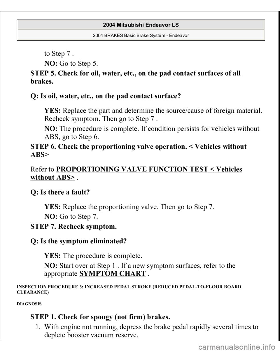
to Step 7 .
NO: Go to Step 5.
STEP 5. Check for oil, water, etc., on the pad contact surfaces of all
brakes.
Q: Is oil, water, etc., on the pad contact surface?
YES: Replace the part and determine the source/cause of foreign material.
Recheck symptom. Then go to Step 7 .
NO: The procedure is complete. If condition persists for vehicles without
ABS, go to Step 6.
STEP 6. Check the proportioning valve operation. < Vehicles without
ABS>
Refer to PROPORTIONING VALVE FUNCTION TEST < Vehicles
without ABS>
.
Q: Is there a fault?
YES: Replace the proportioning valve. Then go to Step 7.
NO: Go to Step 7.
STEP 7. Recheck symptom.
Q: Is the symptom eliminated?
YES: The procedure is complete.
NO: Start over at Step 1 . If a new symptom surfaces, refer to the
appropriate SYMPTOM CHART
.
INSPECTION PROCEDURE 3: INCREASED PEDAL STROKE (REDUCED PEDAL-TO-FLOOR BOARD
CLEARANCE) DIAGNOSIS
STEP 1. Check for spongy (not firm) brakes.
1. With engine not running, depress the brake pedal rapidly several times to
de
plete booster vacuum reserve.
2004 Mitsubishi Endeavor LS
2004 BRAKES Basic Brake System - Endeavor
Page 709 of 3870
Q: Is there a leak?
YES: Check the connection for looseness, corrosion, etc. Clean and repair
as necessary. If leaking in any tube or hose section, replace the complete
tube or hose. Then go to Step 7 .
NO: Go to Step 6.
STEP 6. Check the clearance (too much) between the push rod and
primary piston.
Refer to MASTER CYLINDER ASSEMBLY AND BRAKE BOOSTER
.
Q: Is the clearance outside of specifications?
YES: Adjust the clearance. Then go to Step 7.
NO: Go to Step 7.
STEP 7. Recheck symptom.
Q: Is the symptom eliminated?
YES: The procedure is complete.
NO: Start over at Step 1 . If a new symptom surfaces, refer to the
SYMPTOM CHART
.
INSPECTION PROCEDURE 4: BRAKE DRAG DIAGNOSIS
STEP 1. Check the parking brake operating lever return.
2004 Mitsubishi Endeavor LS
2004 BRAKES Basic Brake System - Endeavor
Page 713 of 3870
STEP 9. Recheck symptom.
Q: Is the symptom eliminated?
YES: The procedure is complete.
NO: Start over at Step 1 . If a new symptom surfaces, refer to the
SYMPTOM CHART
.
INSPECTION PROCEDURE 5: SCRAPING OR GRINDING NOISE WHEN BRAKES ARE APPLIED DIAGNOSIS
STEP 1. Check the front brakes, then rear brakes, for metal-to-metal
condition.
Q: Is the metal-to-metal contact evident?
YES: Repair or replace the components. Then go to Step 6 .
NO: Go to Step 2.
STEP 2. Check for interference between the caliper and wheel.
Q: Is there a interference?
YES: Repair or replace the part. Then go to Step 6 .
NO: Go to Step 3.
STEP 3. Check for interference between the dust cover and brake disc.
2004 Mitsubishi Endeavor LS
2004 BRAKES Basic Brake System - Endeavor
Page 716 of 3870
DIAGNOSI
S
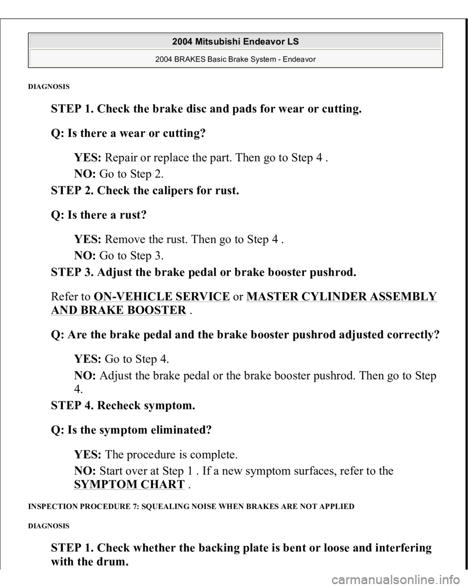
STEP 1. Check the brake disc and pads for wear or cutting.
Q: Is there a wear or cutting?
YES: Repair or replace the part. Then go to Step 4 .
NO: Go to Step 2.
STEP 2. Check the calipers for rust.
Q: Is there a rust?
YES: Remove the rust. Then go to Step 4 .
NO: Go to Step 3.
STEP 3. Adjust the brake pedal or brake booster pushrod.
Refer to ON
-VEHICLE SERVICE
or MASTER CYLINDER ASSEMBLY
AND BRAKE BOOSTER
.
Q: Are the brake pedal and the brake booster pushrod adjusted correctly?
YES: Go to Step 4.
NO: Adjust the brake pedal or the brake booster pushrod. Then go to Step
4.
STEP 4. Recheck symptom.
Q: Is the symptom eliminated?
YES: The procedure is complete.
NO: Start over at Step 1 . If a new symptom surfaces, refer to the
SYMPTOM CHART .
INSPECTION PROCEDURE 7: SQUEALING NOISE WHEN BRAKES ARE NOT APPLIED DIAGNOSIS
STEP 1. Check whether the backing plate is bent or loose and interfering
with the drum
.
2004 Mitsubishi Endeavor LS
2004 BRAKES Basic Brake System - Endeavor
Page 720 of 3870
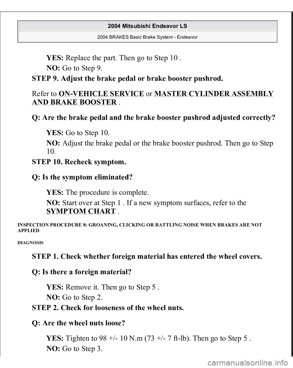
YES: Replace the part. Then go to Step 10 .
NO: Go to Step 9.
STEP 9. Adjust the brake pedal or brake booster pushrod.
Refer to ON
-VEHICLE SERVICE
or MASTER CYLINDER ASSEMBLY
AND BRAKE BOOSTER
.
Q: Are the brake pedal and the brake booster pushrod adjusted correctly?
YES: Go to Step 10.
NO: Adjust the brake pedal or the brake booster pushrod. Then go to Step
10.
STEP 10. Recheck symptom.
Q: Is the symptom eliminated?
YES: The procedure is complete.
NO: Start over at Step 1 . If a new symptom surfaces, refer to the
SYMPTOM CHART .
INSPECTION PROCEDURE 8: GROANING, CLICKING OR RATTLING NOISE WHEN BRAKES ARE NOT
APPLIED DIAGNOSIS
STEP 1. Check whether foreign material has entered the wheel covers.
Q: Is there a foreign material?
YES: Remove it. Then go to Step 5 .
NO: Go to Step 2.
STEP 2. Check for looseness of the wheel nuts.
Q: Are the wheel nuts loose?
YES: Tighten to 98 +/- 10 N.m (73 +/- 7 ft-lb). Then go to Step 5 .
NO: Go to Ste
p 3.
2004 Mitsubishi Endeavor LS
2004 BRAKES Basic Brake System - Endeavor
Page 799 of 3870
Technical Descriptio
n
The cause could be a malfunction of the fan control module power supply or
ground circuit. The cause could also be a malfunction of the fan control module or the PCM.
Troubleshooting Hints
Malfunction of fusible link. Malfunction of fan control relay. Malfunction of MFI relay. Malfunction of radiator fan motor. Malfunction of condenser fan motor. Malfunction of fan control module. Malfunction of PCM. Damaged wiring harness or connector.
Diagnosis 1. Disconnect fan control module connector A-23. See Fig. 7
. Measure for
voltage between terminal No. 3 (harness side of the connector) and ground
when ignition switch is turned to the ON position. If battery voltage is not
achieved, go to next step. If battery voltage is achieved, go to step 8 .
2. Check fan control relay. See FAN CONTROL RELAY under
COMPONENTS TESTS. If fan control relay is okay, go to next step. If fan
control relay is not okay, replace it and retest.
3. Check the MFI relay. See MULTI
-PORT FUEL INJECTION (MFI)
RELAY
under COMPONENT TESTS. If MFI relay is okay, go to next step. If
MFI relay is not okay, replace it and retest.
4. Check for harness damage in Black/Yellow wire between fusible link No. 2
and terminal No. 4 of fan control relay connector A-10X. See Fig. 8
. If wire is
okay, go to next step. If wire is damaged, repair or replace as necessary and
retest.
5. Check for harness damage in Blue wire between terminal No. 2 of fan control
rela
y connector
A-10X and terminal No. 3 of fan control module connector A-
2004 Mitsubishi Endeavor Limited
2004 ENGINE COOLING Electric Cooling Fans - Endeavor
Page 807 of 3870
Fig. 12: Identifying Power Plant ECU Check Harness (MB991923)
Courtesy of MITSUBISHI MOTOR SALES OF AMERICA.
TEST B: RADIATOR FAN & CONDENSER FAN DO NOT CHANGE SPEED OR STOP Technical Description The fan control module has variable control of the radiator fan motor and the
condenser fan motor speeds using signals transmitted from the PCM. Troubleshooting Hints
Malfunction of fan control relay. Malfunction of fan control module. Malfunction of PCM.
Diagnosis 1. Check the fan control relay. See FAN CONTROL RELAY
under
COMPONENT TESTS. If fan control relay is okay, go to next step. If fan
control module is damaged, repair or replace as necessary and retest.
2. Check the harness wire between terminal No. 2 of fan control relay connector
A-10X and terminal No. 3 of fan control module connector A-18. See Fig. 7
and Fig. 8
. If wiring is damaged, repair or replace as necessary and retest. If
wiring is okay, go to next step.
3. Disconnect all the connectors from the PCM. Connect Power Plant ECU Check
Harness (MB991923
) between the PCM and the bod
y-side harness connector.
NOTE: If the engine coolant temperature reaches 230°F (110°C) or
higher, the radiator fan control runs the radiator fan for up
to 5 minutes even after the ignition switch is turned to the
LOCK position. The fan stops its rotation when the engine
coolant temperature decreases to 230°F (110°C) or l ower.
NOTE: Measure the output circuit voltage at terminal No. 10 of
PCM connector B-18 by using Power Plant ECU Check
Harness (MB991923). See Fig. 11
and Fig. 12
.
2004 Mitsubishi Endeavor Limited
2004 ENGINE COOLING Electric Cooling Fans - Endeavor