Page 237 of 3870
2. Turn the ignition switch to the "ON" position.
3. Check whether combination meter DTC U1102 has been set.
Q: Is combination meter DTC U1102 set?
YES: Replace the hydraulic unit (integrated with ABS-ECU)
NO: Replace the combination meter.
INSPECTION PROCEDURE 5: FAULTY ABS OPERATION TECHNICAL DESCRIPTION (COMMENT) The cause depends on driving and road surface conditions, so diagnosis may be
difficult. However, if no diagnostic trouble code is displayed, carry out the
following inspection. TROUBLESHOOTING HINTS (THE MOST LIKELY CAUSES FOR THIS CASE:)
Malfunction of the hydraulic unit
DIAGNOSIS Check the hydraulic unit (Refer to POINTS IN WAVEFORM MEASUREMENT
). If the hydraulic unit (integrated with ABS-ECU) is
malfunctioning, replace it. Then check that the malfunction symptom is eliminated.
STEP 1. Hydraulic unit check
Refer to POINTS IN WAVEFORM MEASUREMENT
.
Q: Is the hydraulic unit normal?
YES: Go to Step 2.
NO: Connect the brake pipes correctly, repair the external brake lines, or
replace the hydraulic unit.
STEP 2. Verify that the condition described by the customer exists.
Q: Can any faults be found with the brake operation?
2004 Mitsubishi Endeavor LS
2004 BRAKES Anti-Lock Braking System (ABS) - Endeavor
Page 241 of 3870
TERMINAL VOLTAGE CHECK CHART Required Special Tool:
MB991970: ABS Check Harness
1. Disconnect the ABS-ECU connector A-02, and then use special tool
MB991970 to measure the voltages between terminals (2) and each terminal
other than terminal (18) as well as between terminal (18) and each terminal
other than terminal
(2). NOTE: For vehicles with ASC, refer to TCL/ASC DIAGNOSIS
.
2004 Mitsubishi Endeavor LS
2004 BRAKES Anti-Lock Braking System (ABS) - Endeavor
Page 255 of 3870
4. After checking that the selector lever is in "P" range, start the engine.
5. Select "Interactive Diagnosis" from the start-up screen.
6. Select "System Select."
7. Choose "ABS" from the "CHASSIS" tab.
8. Select "Actuator Test" from "ABS" screen
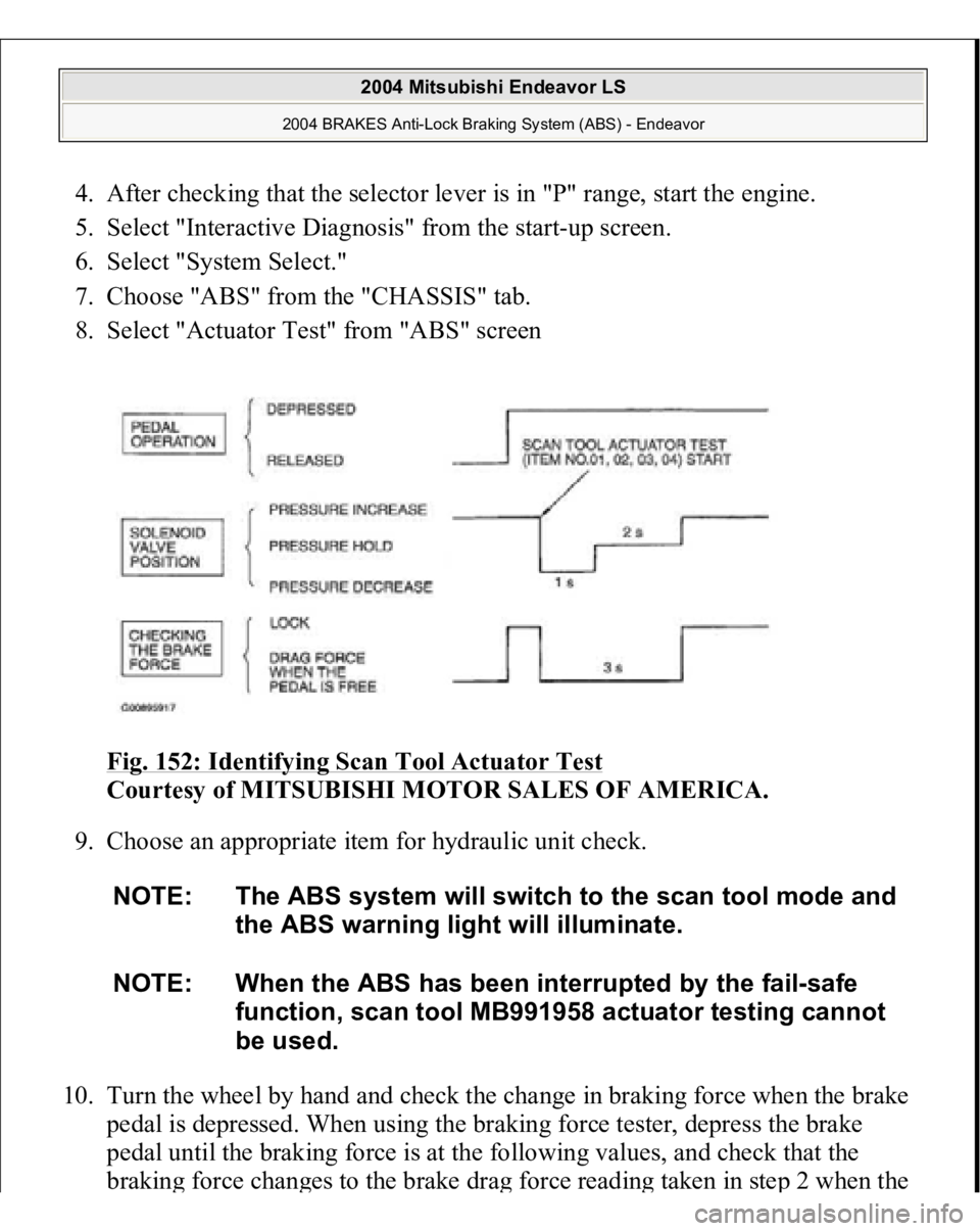
Fig. 152: Identifying Scan Tool Actuator Test
Courtesy of MITSUBISHI MOTOR SALES OF AMERICA.
9. Choose an appropriate item for hydraulic unit check.
10. Turn the wheel by hand and check the change in braking force when the brake
pedal is depressed. When using the braking force tester, depress the brake
pedal until the braking force is at the following values, and check that the
brakin
g force chan
ges to the brake dra
g force readin
g taken in ste
p 2 when the
NOTE: The ABS system will switch to the scan tool mode and
the ABS warning light will illuminate.
NOTE: When the ABS has been interrupted by the fail-safe
function, scan tool MB991958 actuator testing cannot
be used.
2004 Mitsubishi Endeavor LS
2004 BRAKES Anti-Lock Braking System (ABS) - Endeavor
Page 256 of 3870
actuator is force-driven. The result should be as shown in the diagram above.
HYDRAULIC UNIT CHECK
11. If the result of inspection is abnormal, repair according to the Diagnosis Table
below.
Fig. 153: Diagnosis Table
Courtesy of MITSUBISHI MOTOR SALES OF AMERICA.
12. After inspection, disconnect scan tool MB991958 immediately after turning the
ignition switch to the "LOCK" (OFF) position.
IN THE EVENT OF A DISCHARGED BATTERY
Front wheel
785 - 981 N (176 - 220 lb.)
Rear wheel
588 - 784 N (132 - 176 lb.)
WARNING:If the ABS is not operating, the vehicle will be
unstable during braking, Do not drive the vehicle
2004 Mitsubishi Endeavor LS
2004 BRAKES Anti-Lock Braking System (ABS) - Endeavor
Page 277 of 3870
Such shorts can damage fuses or components and may cause a second
Diagnostic Trouble Code (DTC) to set, making diagnosis of original problem
more difficult. Never use an analog volt/ohm meter or test light in place of a Digital Volt/Ohm
Meter (DVOM). Use only a DVOM with a maximum test current of 2 mA
(milliamps) at minimum range of resistance measurement. If SRS is not fully functional for any reason, DO NOT drive vehicle until
system is repaired and fully functional. DO NOT remove bulbs, modules,
sensors, or other components or in any way disable system from operating
normally. If SRS is not functional, park vehicle until repairs are made.
DISABLING & ACTIVATING AIR BAG SYSTEM To disable system, turn ignition off. Disconnect negative battery cable. Shield cable
end with electrical tape. Wait at least 60 seconds before servicing air bag system.
To activate system, reconnect negative battery cable. Check system operation. See SYSTEM OPERATION CHECK
.
DISPOSAL PROCEDURES DEPLOYED AIR BAG OR SEAT BELT PRETENSIONER Place deployed component in a strong plastic bag and seal tightly. Dispose of
component as you would any other part. No other special disposal procedure is
required. UNDEPLOYED AIR BAG OR SEAT BELT PRETENSIONER
WARNING:Accidental air bag deployment is possible. Personal
injury may result. Read and follow all WARNINGS
and AIR BAG SAFETY PRECAUTIONS
before
working on air bag system or related components.
NOTE: Undeployed air bag modules must be deployed before
disposal. Disposing of an undeployed air bag may violate
federal, state and/or local laws. This also applies to vehicles
that are to be scrapped.
2004 Mitsubishi Endeavor Limited
2004 ACCESSORIES/SAFETY EQUIPMENT Mitsubishi - Air Bag Restraint Systems
Page 300 of 3870
1. Turn ignition on. If AIR BAG warning light comes on for 7 seconds and then
goes off, SRS is functioning properly. If AIR BAG warning light does not
function as described, turn ignition off. If AIR BAG warning light malfunction
or scan tool communication problems are encountered, diagnose malfunction
using appropriate table. SeeSCAN TOOL COMMUNICATION
SYMPTOMS (SINGLE
-STAGE AIR BAG SYSTEMS)
and SCAN TOOL
COMMUNICATION SYMPTOMS (DUAL
-STAGE AIR BAG
SYSTEMS)
tables.
2. Utilizing a laptop computer, check for Diagnostic Trouble Codes (DTCs) by
connecting Scan Tool (MB991958) to Data Link Connector (DLC), located
under left side of instrument panel, using Vehicle Communication Interface
(MB991824), USB Cable (MB991827) and Main Harness (MB991911). See
Fig. 18
. Turn ignition on and follow instructions provided with scan tool.
Diagnose displayed DTCs for appropriate air bag system. See SCAN TOOL
COMMUNICATION SYMPTOMS (SINGLE
-STAGE AIR BAG
SYSTEMS)
and SCAN TOOL COMMUNICATION SYMPTOMS
(DUAL
-STAGE AIR BAG SYSTEMS)
. When diagnosis and repairs are
com
plete, erase DTCs.
2004 Mitsubishi Endeavor Limited
2004 ACCESSORIES/SAFETY EQUIPMENT Mitsubishi - Air Bag Restraint Systems
Page 439 of 3870

passenger-side front seat. Measure resistance between ground and harness-side
of connector D-38, terminal No. 1. See Fig. 45
. If resistance is 2 ohms or less,
go to next step. If resistance is more than 2 ohms, repair short to ground. Go to
step 8 .
4. Turn ignition on. Measure voltage between ground and harness-side of
connector D-38, terminal No. 2. If voltage is about 12 volts, go next step. If
voltage is not about 12 volts, go to step 8 .
5. Inspect Black/White wire for an open or short circuit between connector D-38,
terminal No. 2 and ignition switch connector C-308, terminal No. 2. See Fig.
30 . If wire is okay, go to step 8 . If wire is not okay, replace wire harness
between occupant classification ECU and ignition switch connector C-308. Go
to step 8 .
6. Disconnect SRS ECU connector C-25. See SRS ELECTRONIC CONTROL UNIT (SRS ECU)
under REMOVAL & INSTALLATION. Inspect Sky Blue
wire for an open or short circuit between connector D-38, terminal No. 3 and
SRS ECU connector C-25, terminal No. 66. See Fig. 33
. If wire is okay,
reconnect SRS components. Erase, then retrieve DTCs. If DTC B1545 is
retrieved, replace front seat slide adjuster. Go to next step. If wire harness is
not okay, replace wire harness. Go to step 8 .
7. Erase DTCs. Turn ignition on. If DTC B1545 is retrieved, replace SRS ECU.
Go to next step. If DTC B1545 is not retrieved, diagnosis is complete.
8. Erase, then retrieve DTCs. If DTC B1545 is retrieved, go to step 1 . If DTC
B1545 is not retrieved, system is normal at this time.
2004 Mitsubishi Endeavor Limited
2004 ACCESSORIES/SAFETY EQUIPMENT Mitsubishi - Air Bag Restraint Systems
Page 441 of 3870
terminal No. 2 and ignition switch connector C-308, terminal No. 2. If wire is
okay, go to step 8 . If wire is not okay, replace wire harness between occupant
classification ECU and ignition switch connector C-308. Go to step 8 .
6. Disconnect SRS ECU connector C-25. See SRS ELECTRONIC CONTROL UNIT (SRS ECU)
under REMOVAL & INSTALLATION. See Fig. 30
.
Inspect Sky Blue wire for an open or short circuit between connector D-38,
terminal No. 3 and SRS ECU connector C-25, terminal No. 66. See Fig. 33
. If
wire is okay, reconnect SRS components. Erase, then retrieve DTCs. If DTC
B1545 is retrieved, replace front seat slide adjuster. Go to next step. If wire
harness is not okay, replace wire harness. Go to step 8 .
7. Erase DTCs. Turn ignition on. If DTC B1546 is retrieved, replace SRS ECU.
Go to next step. If DTC B1546 is not retrieved, diagnosis is complete.
8. Erase, then retrieve DTCs. If DTC B1546 is retrieved, go to step 1 . If DTC
B1546 is not retrieved, system is normal at this time.
DTC B1547: CUT OFF FOR PASSENGER-SIDE AIR BAG MODULE 1. Connect scan tool to Data Link Connector (DLC). See INITIAL SRS
DIAGNOSTIC PROCEDURE
under DIAGNOSTICS. If scan tool is able to
diagnose CAN bus lines and CAN bus lines are satisfactory, go to next step. If
scan tool cannot diagnose CAN bus lines, repair CAN bus lines. Go to next
step.
2. Erase, then retrieve DTCs. Turn ignition off. If DTC B1547 is retrieved, go to
next step. If DTC B1547 is not retrieved, an intermittent condition may exist.
3. If DTCs other than DTC B1457 are retrieved, diagnose indicated DTC. See
DIAGNOSTIC TROUBLE CODES (DTCS) IDENTIFICATION WITH
SINGLE
-STAGE AIR BAG SYSTEM
table. If only DTC B1547 is
retrieved, go to next step.
4. Using scan tool, erase, then retrieve DTCs. If DTC B1547 is retrieved, replace
SRS ECU. See SRS ELECTRONIC CONTROL UNIT (SRS ECU)
under
REMOVAL & INSTALLATION. If DTC B1547 is not retrieved, diagnosis is
complete.
DTC B1552: CHANGING CIRCUIT SHORT 1. Connect scan tool to Data Link Connector
(DLC
). SeeINITIAL SRS
2004 Mitsubishi Endeavor Limited
2004 ACCESSORIES/SAFETY EQUIPMENT Mitsubishi - Air Bag Restraint Systems