Page 2654 of 3870
Fig. 106: Displaying "Progress"
Courtesy of MITSUBISHI MOTOR SALES OF AMERICA.
10. The number of keys currently registered will be displayed. To register an
additional key, replace the ignition key with the next key to be registered
within five seconds. Key ID registration screen will be displayed, then register
another key.
11. This completes the registration operation. Turn the ignition switch
"LOCK" (OFF) and leave it off for approximately ten seconds.
12. Check that the engine can be started with each of the ignition keys.
13. Check that the immobilizer s
ystem DTC and MFI s
ystem DTC did not set.
NOTE: A maximum of eight different keys can be registered.
2004 Mitsubishi Endeavor LS
2004 BODY & ACCESSORIES Ignition Switch - Endeavor
Page 2659 of 3870
Fig. 110: Displaying "Transponder ID Addition" (3 Of 3)
Courtesy of MITSUBISHI MOTOR SALES OF AMERICA.
8. This completes the registration operation. Turn the ignition switch
"LOCK" (OFF) and leave it off for approximately ten seconds.
9. Check that the engine can be started with each of the ignition keys.
10. Check that the immobilizer system DTC and MFI system DTC did not set.
11. If not DTC is shown, terminate scan tool MB991958.
12. Turn the ignition switch to "LOCK" (OFF) position.
13. Disconnect scan tool MB991958.
REGISTRATION OF ADDITIONAL KEY(S) WITHOUT USING THE SCAN TOOL
NOTE: A maximum of eight different keys can be registered.
2004 Mitsubishi Endeavor LS
2004 BODY & ACCESSORIES Ignition Switch - Endeavor
Page 2660 of 3870
If the scan tool is not available, new key(s) can be registered by operating two keys
which have been registered to the vehicle (A maximum of eight keys can be
registered to one vehicle). Follow the procedure below to register new key(s) to the
vehicle.
1. Turn "ON" the ignition switch by using the first registered key (key A), and
wait for five seconds.
2. Remove the first registered key (key A).
3. Insert the second registered ignition key (key B), and turn it to the ON position.
4. After approximately 10 seconds the immobilizer indicator will start blinking,
and then additional registration mode is entered.
5. Check the immobilizer indicator starts blinking, and then remove the second
re
gistered ke
y (key B).
NOTE: The registered key is the key that allows you to start the
engine.
2004 Mitsubishi Endeavor LS
2004 BODY & ACCESSORIES Ignition Switch - Endeavor
Page 2662 of 3870

Courtesy of MITSUBISHI MOTOR SALES OF AMERICA
.
8. If a new ignition key is registered further, repeat steps 1 to 7 above.
A maximum of eight ignition keys can be registered to one vehicle (If you
attempt to register the ninth key, the immobilizer-ECU rejects the key). If any
of the following conditions are satisfied, the additional key registration mode
will terminate:
The immobilizer indicator starts blinking for more than 30 seconds. After the ignition key has been turned to the "LOCK" (OFF), the engine
control relay is turned off. The scan tool has started communicating with vehicle systems.
9. After the registration mode has terminated, the additionally registered key(s)
should allow you to start the engine.
TRANSPONDER LOCK CHECK Required Special Tools:
MB991958: Scan Tool (MUT-III Sub Assembly)
MB991824: Vehicle Communication Interface (V.C.I.) MB991827: MUT-III USB Cable MB991910: MUT-III Main Harness A (Vehicles with CAN
communication system)
Follow the procedure below to judge if the ignition key can be overwritten (i.e. the
ignition key is correct) or not.
1. Connect the scan tool MB991958 to the data link connector. CAUTION: To prevent damage to scan tool MB991958, always
turn the ignition switch to "LOCK" (OFF) position
before connecting or disconnecting scan tool
MB991958.
2004 Mitsubishi Endeavor LS
2004 BODY & ACCESSORIES Ignition Switch - Endeavor
Page 2683 of 3870

2004 ENGINE
Ignition System - Endeavor
GENERAL DESCRIPTION This system is provided with six ignition coils with built-in ignition power
transistors for each of the cylinders.
Interruption of the primary current flowing in the primary side of ignition coil
generates a high voltage in the secondary side of ignition coil.
The powertrain control module (PCM) controls the three ignition power transistors
to turn them alternately ON and OFF. This causes the primary currents in the
ignition coils to be alternately interrupted and allowed to flow to fire the cylinders
in the order 1-2-3-4-5-6.
The PCM determines which ignition coil should be controlled by means of the
signals from the camshaft position sensor which is incorporated in the camshaft and
from the crankshaft position sensor which is incorporated in the crankshaft.
It also detects the crankshaft position to provide ignition at the most appropriate
timing in response to the engine operation conditions.
When the engine is cold or operated at high altitudes, the ignition timing is slightly
advanced to
provide o
ptimum
performance.
2004 Mitsubishi Endeavor Limited 2004 ENGINE Ignition System - Endeavor
2004 Mitsubishi Endeavor Limited 2004 ENGINE Ignition System - Endeavor
Page 2684 of 3870
Fig. 1: Ignition System Circuit Diagram
Courtesy of MITSUBISHI MOTOR SALES OF AMERICA.
SPECIAL TOOLS Fig. 2: Identifying Special Tool
Courtesy of MITSUBISHI MOTOR SALES OF AMERICA.
ON-VEHICLE SERVICE KNOCK CONTROL SYSTEM CHECK Check the knock sensor circuit if diagnostic trouble code, No. P0325 is shown.
Refer to DTC P0325: KNOCK SENSOR CIRCUIT MALFUNCTION
.
2004 Mitsubishi Endeavor Limited 2004 ENGINE Ignition System - Endeavor
Page 2685 of 3870
IGNITION COIL CHEC
K
Check by the following procedure, and replace the coil if there is a malfunction. PRIMARY COIL AND IGNITION POWER TRANSISTOR CONTINUITY CHECK Fig. 3: Checking Primary Coil And Ignition Power Transistor
Courtesy of MITSUBISHI MOTOR SALES OF AMERICA.
NOTE: An analog-type ohmmeter should be used.
NOTE: Connect the negative probe of the ohmmeter to terminal 1.
CAUTION: This test must be performed quickly (in less than 10
seconds) to prevent coil from burning and ignition
power transistor from breaking.
2004 Mitsubishi Endeavor Limited 2004 ENGINE Ignition System - Endeavor
Page 2686 of 3870

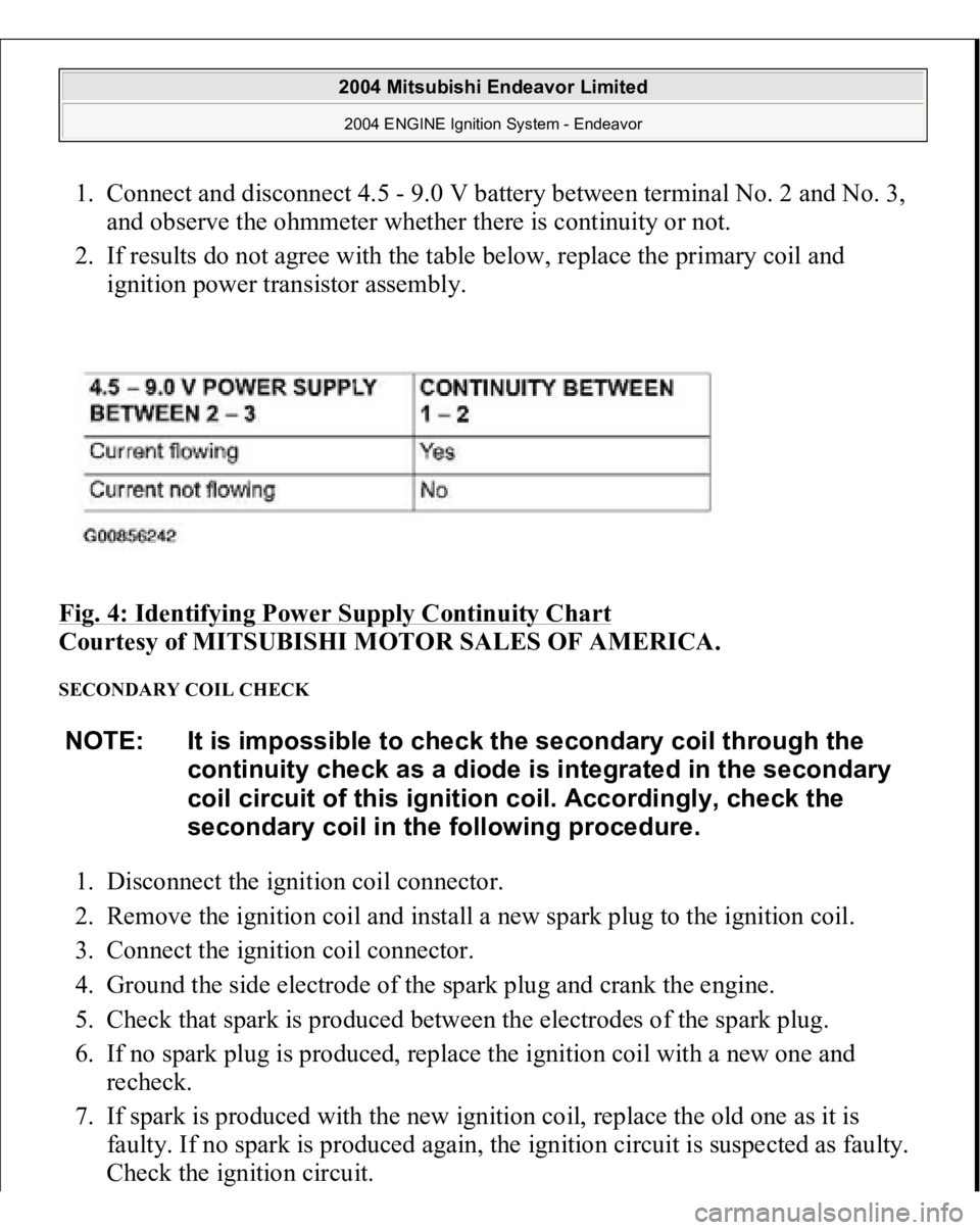
1. Connect and disconnect 4.5 - 9.0 V battery between terminal No. 2 and No. 3,
and observe the ohmmeter whether there is continuity or not.
2. If results do not agree with the table below, replace the primary coil and
ignition power transistor assembly.
Fig. 4: Identifying Power Supply Continuity Chart
Courtesy of MITSUBISHI MOTOR SALES OF AMERICA.
SECONDARY COIL CHECK 1. Disconnect the ignition coil connector.
2. Remove the ignition coil and install a new spark plug to the ignition coil.
3. Connect the ignition coil connector.
4. Ground the side electrode of the spark plug and crank the engine.
5. Check that spark is produced between the electrodes of the spark plug.
6. If no spark plug is produced, replace the ignition coil with a new one and
recheck.
7. If spark is produced with the new ignition coil, replace the old one as it is
faulty. If no spark is produced again, the ignition circuit is suspected as faulty.
Check the ignition circuit. NOTE: It is impossible to check the secondary coil through the
continuity check as a diode is integrated in the secondary
coil circuit of this ignition coil. Accordingly, check the
secondary coil in the following procedure.
2004 Mitsubishi Endeavor Limited 2004 ENGINE Ignition System - Endeavor