Page 707 of 3870

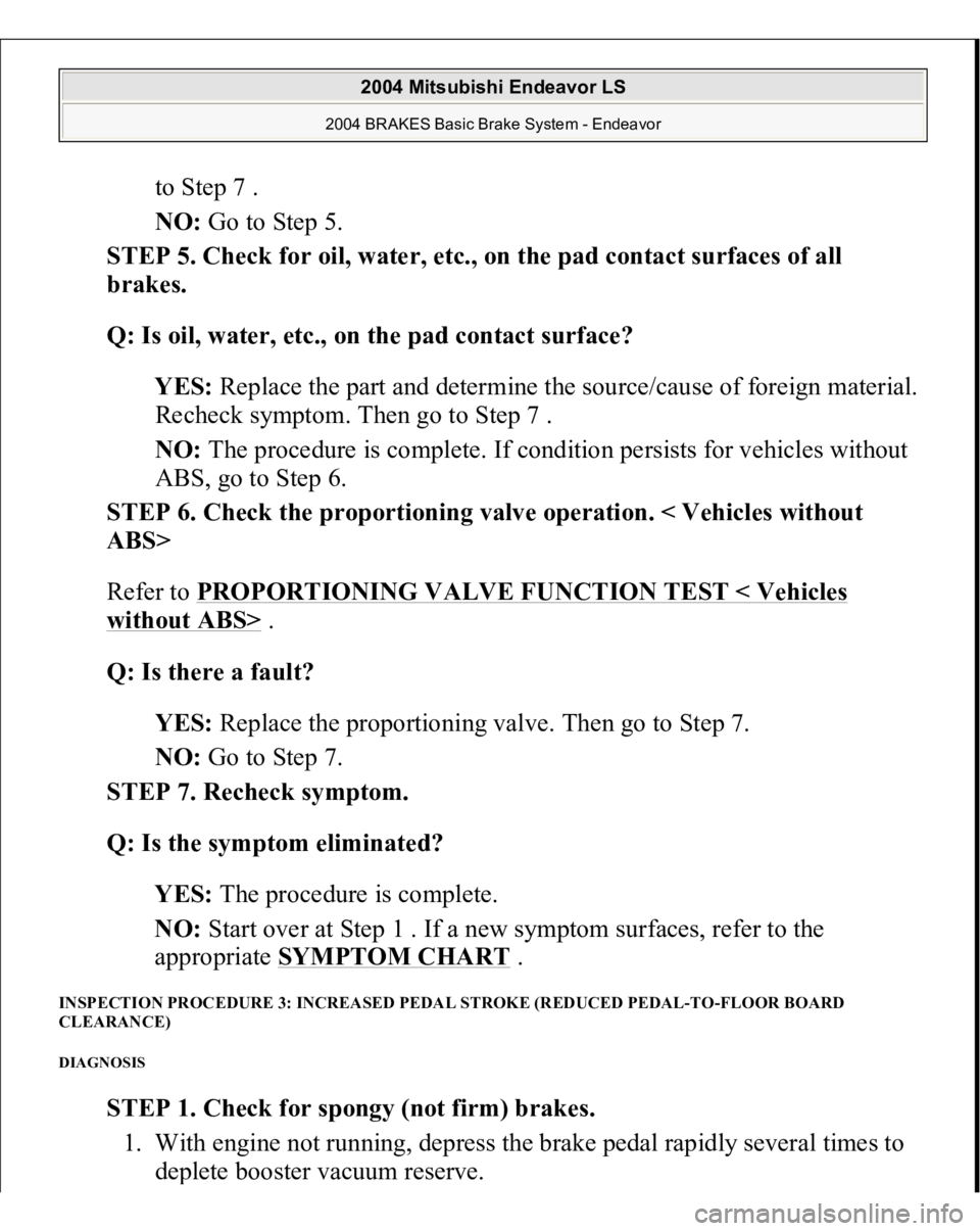
to Step 7 .
NO: Go to Step 5.
STEP 5. Check for oil, water, etc., on the pad contact surfaces of all
brakes.
Q: Is oil, water, etc., on the pad contact surface?
YES: Replace the part and determine the source/cause of foreign material.
Recheck symptom. Then go to Step 7 .
NO: The procedure is complete. If condition persists for vehicles without
ABS, go to Step 6.
STEP 6. Check the proportioning valve operation. < Vehicles without
ABS>
Refer to PROPORTIONING VALVE FUNCTION TEST < Vehicles
without ABS>
.
Q: Is there a fault?
YES: Replace the proportioning valve. Then go to Step 7.
NO: Go to Step 7.
STEP 7. Recheck symptom.
Q: Is the symptom eliminated?
YES: The procedure is complete.
NO: Start over at Step 1 . If a new symptom surfaces, refer to the
appropriate SYMPTOM CHART
.
INSPECTION PROCEDURE 3: INCREASED PEDAL STROKE (REDUCED PEDAL-TO-FLOOR BOARD
CLEARANCE) DIAGNOSIS
STEP 1. Check for spongy (not firm) brakes.
1. With engine not running, depress the brake pedal rapidly several times to
de
plete booster vacuum reserve.
2004 Mitsubishi Endeavor LS
2004 BRAKES Basic Brake System - Endeavor
Page 775 of 3870
torque in the forward direction. Record hub torque with pads removed.
Fig. 53: Measuring Hub Torque Without Pads
Courtesy of MITSUBISHI MOTOR SALES OF AMERICA.
2. After re-installing the caliper support to the knuckle, install the pad clips and
the pads to the caliper support.
3. Clean the piston and insert into cylinder with special tool MB990520.
4. Be careful that the piston boot does not become caught, when lowering the
caliper assembly and installing the lock pin bolt.
5. Check the brake drag force as follows.
CAUTION: Do not let any oil, grease or other contamination
get onto the friction surfaces of the pads and
brake discs.
2004 Mitsubishi Endeavor LS
2004 BRAKES Basic Brake System - Endeavor
Page 1068 of 3870

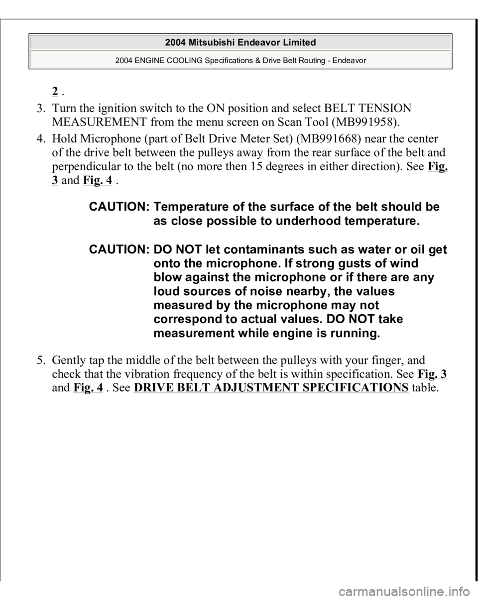
2 .
3. Turn the ignition switch to the ON position and select BELT TENSION
MEASUREMENT from the menu screen on Scan Tool (MB991958).
4. Hold Microphone (part of Belt Drive Meter Set) (MB991668) near the center
of the drive belt between the pulleys away from the rear surface of the belt and
perpendicular to the belt (no more then 15 degrees in either direction). See Fi
g.
3 and Fig. 4
.
5. Gently tap the middle of the belt between the pulleys with your finger, and
check that the vibration frequency of the belt is within specification. See Fig. 3
and Fig. 4
. See DRIVE BELT ADJUSTMENT SPECIFICATIONS
table.
CAUTION: Temperature of the surface of the belt should be
as close possible to underhood temperature.
CAUTION: DO NOT let contaminants such as water or oil get
onto the microphone. If strong gusts of wind
blow against the microphone or if there are any
loud sources of noise nearby, the values
measured by the microphone may not
correspond to actual values. DO NOT take
measurement while engine is running.
2004 Mitsubishi Endeavor Limited
2004 ENGINE COOLING Specifications & Drive Belt Routing - Endeavor
Page 1088 of 3870
Fig. 6: Inserting Rag
Courtesy of MITSUBISHI MOTOR SALES OF AMERICA.
INSTALLATION SERVICE POINT << A>> PROPELLER SHAFT ASSEMBLY INSTALLATION
CAUTION:
Do not dama
ge the oil seal lips on the transfer ca
s
2004 Mitsubishi Endeavor LS
2004 DRIVELINE/AXLE Propeller Shaft - Endeavor
Page 1089 of 3870
If reusing the propeller shaft, align the mating marks of differential companion
flan
ge and
propeller shaft assembl
y to install.
Fig. 7: Locating Oil Seal Lips On Transfer Case
Courtes
y of MITSUBISHI MOTOR SALES OF AME
R
Remove oil and grease from the threads of the
mounting bolts and nuts before ti
ghtenin
g, or the
y
loosen. Be careful not to bend the
joint portion when rem
o
the propeller shaft, because this will damage the j
o
boot.
2004 Mitsubishi Endeavor LS
2004 DRIVELINE/AXLE Propeller Shaft - Endeavor
Page 1095 of 3870

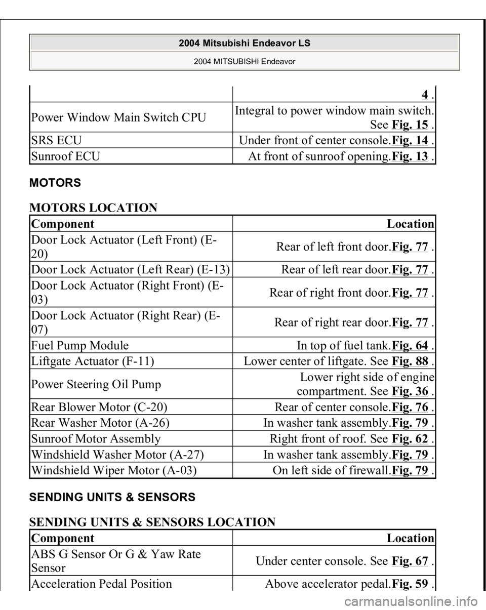
MOTORS MOTORS LOCATION SENDING UNITS & SENSORS SENDING UNITS & SENSORS LOCATION
4 .
Power Window Main Switch CPU
Integral to power window main switch.
See Fig. 15
.
SRS ECU
Under front of center console.Fig. 14
.
Sunroof ECU
At front of sunroof opening.Fig. 13
.
Component
Location
Door Lock Actuator (Left Front) (E-
20)
Rear of left front door.Fig. 77
.
Door Lock Actuator (Left Rear) (E-13)
Rear of left rear door.Fig. 77
.
Door Lock Actuator (Right Front) (E-
03)
Rear of right front door.Fig. 77
.
Door Lock Actuator (Right Rear) (E-
07)
Rear of right rear door.Fig. 77
.
Fuel Pump Module
In top of fuel tank.Fig. 64
.
Liftgate Actuator (F-11)
Lower center of liftgate. See Fig. 88
.
Power Steering Oil Pump
Lower right side of engine
compartment. See Fig. 36
.
Rear Blower Motor (C-20)
Rear of center console.Fig. 76
.
Rear Washer Motor (A-26)
In washer tank assembly.Fig. 79
.
Sunroof Motor Assembly
Right front of roof. See Fig. 62
.
Windshield Washer Motor (A-27)
In washer tank assembly.Fig. 79
.
Windshield Wiper Motor (A-03)
On left side of firewall.Fig. 79
.
Component
Location
ABS G Sensor Or G & Yaw Rate
Sensor
Under center console. See Fig. 67
.
Acceleration Pedal Position
Above accelerator pedal.Fig. 59
.
2004 Mitsubishi Endeavor LS
2004 MITSUBISHI Endeavor
Page 1099 of 3870

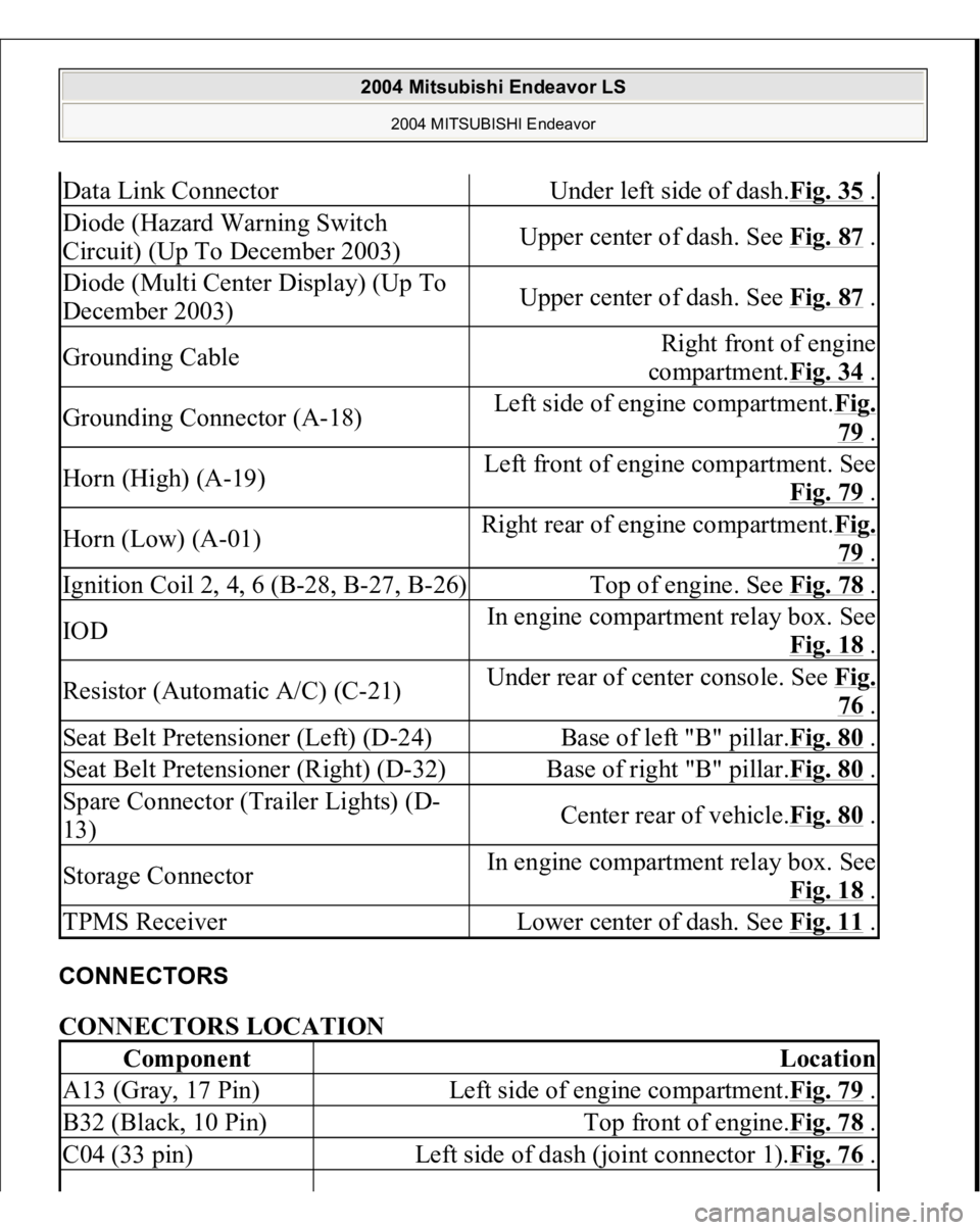
CONNECTORS CONNECTORS LOCATION Data Link Connector
Under left side of dash.Fig. 35
.
Diode (Hazard Warning Switch
Circuit) (Up To December 2003)
Upper center of dash. See Fig. 87
.
Diode (Multi Center Display) (Up To
December 2003)
Upper center of dash. See Fig. 87
.
Grounding Cable
Right front of engine
compartment.Fig. 34
.
Grounding Connector (A-18)
Left side of engine compartment.Fig.
79 .
Horn (High) (A-19)
Left front of engine compartment. See
Fig. 79
.
Horn (Low) (A-01)
Right rear of engine compartment.Fi
g.
79 .
Ignition Coil 2, 4, 6 (B-28, B-27, B-26)
Top of engine. See Fig. 78
.
IOD
In engine compartment relay box. See
Fig. 18
.
Resistor (Automatic A/C) (C-21)
Under rear of center console. See Fi
g.
76 .
Seat Belt Pretensioner (Left) (D-24)
Base of left "B" pillar.Fig. 80
.
Seat Belt Pretensioner (Right) (D-32)
Base of right "B" pillar.Fig. 80
.
Spare Connector (Trailer Lights) (D-
13)
Center rear of vehicle.Fig. 80
.
Storage Connector
In engine compartment relay box. See
Fig. 18
.
TPMS Receiver
Lower center of dash. See Fig. 11
.
Component
Location
A13 (Gray, 17 Pin)
Left side of engine compartment.Fig. 79
.
B32 (Black, 10 Pin)
Top front of engine.Fig. 78
.
C04 (33 pin)
Left side of dash (joint connector 1).Fig. 76
.
2004 Mitsubishi Endeavor LS
2004 MITSUBISHI Endeavor
Page 1193 of 3870
DIAGNOSI
S
STEP 1. Remove the radiator cap and check for coolant contamination.
Q: Is the coolant contaminated with rust and oil?
YES: Replace it. Refer to ENGINE COOLANT REPLACEMENT
.
NO: There is no action to be taken. Go to Step 2.
STEP 2. Check the radiator cap valve opening pressure.
1. Use a cap adapter to attach the cap to the tester.
2. Increase the pressure until the gauge indicator stops moving.
Minimum limit: 83 kPa (12 psi)
Standard value: 93 - 123 kPa (14 - 18 psi)
NOTE: Be sure that the cap is clean before testing. Rust or
other foreign material on the cap seal will cause an
improper reading.
2004 Mitsubishi Endeavor Limited 2004 ENGINE Engine Cooling - Endeavor