Page 72 of 3870

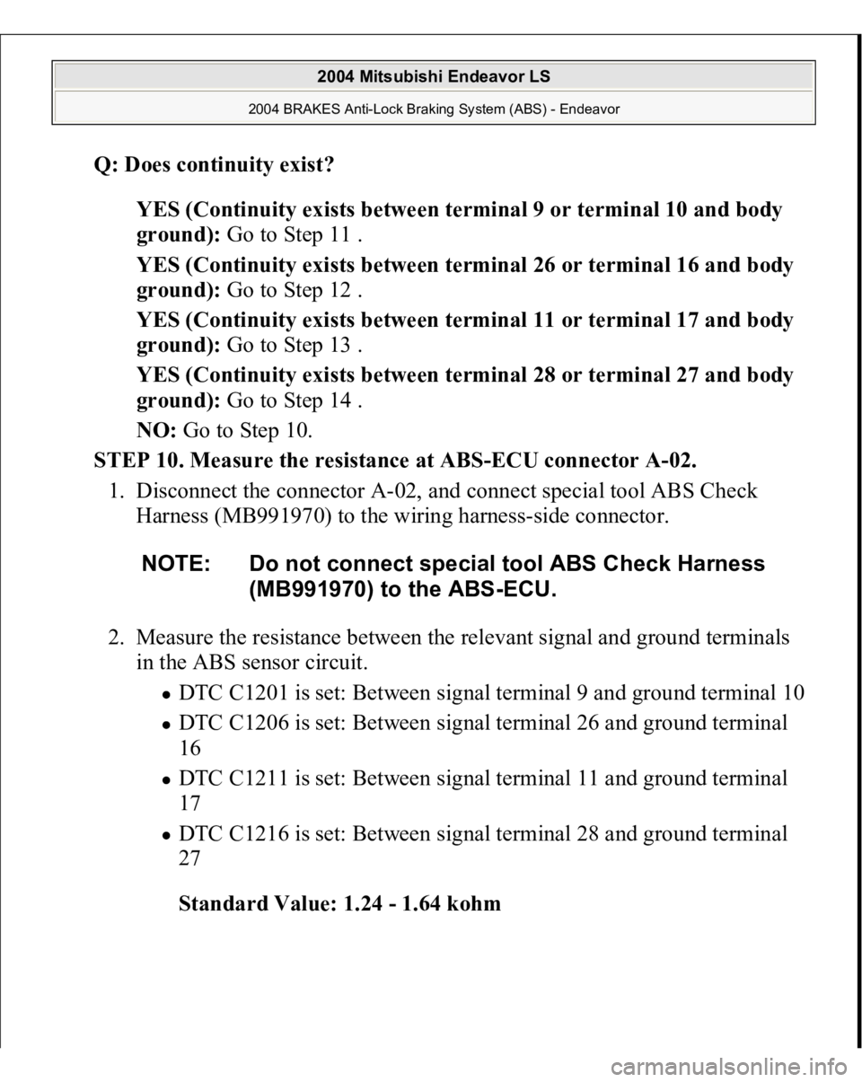
Q: Does continuity exist?
YES (Continuity exists between terminal 9 or terminal 10 and body
ground): Go to Step 11 .
YES (Continuity exists between terminal 26 or terminal 16 and body
ground): Go to Step 12 .
YES (Continuity exists between terminal 11 or terminal 17 and body
ground): Go to Step 13 .
YES (Continuity exists between terminal 28 or terminal 27 and body
ground): Go to Step 14 .
NO: Go to Step 10.
STEP 10. Measure the resistance at ABS-ECU connector A-02.
1. Disconnect the connector A-02, and connect special tool ABS Check
Harness (MB991970) to the wiring harness-side connector.
2. Measure the resistance between the relevant signal and ground terminals
in the ABS sensor circuit.
DTC C1201 is set: Between signal terminal 9 and ground terminal 10 DTC C1206 is set: Between signal terminal 26 and ground terminal
16 DTC C1211 is set: Between signal terminal 11 and ground terminal
17 DTC C1216 is set: Between signal terminal 28 and ground terminal
27
Standard Value: 1.24 - 1.64 kohm NOTE: Do not connect special tool ABS Check Harness
(MB991970) to the ABS-ECU.
2004 Mitsubishi Endeavor LS
2004 BRAKES Anti-Lock Braking System (ABS) - Endeavor
Page 74 of 3870
Q: Is the resistance between terminals 16 and 26, 9 and 10, 27 and 28, or
11 and 17 within the standard value?
YES (When resistance between all terminals are within the standard
value): Go to Step 15 .
NO (When resistance between terminals 9 and 10 is not within the
standard value): Go to Step 11.
NO (When resistance between terminals 16 and 26 is not within the
standard value): Go to Step 12 .
NO (When resistance between terminals 11 and 17 is not within the
standard value): Go to Step 13 .
NO (When resistance between terminals 27 and 28 is not within the
standard value): Go to Step 14 .
STEP 11. Check ABS-ECU connector A-02 and ABS sensor < front: RH >
connector A-31 for loose, corroded or damaged terminals, or terminals
pushed back in the connector.
2004 Mitsubishi Endeavor LS
2004 BRAKES Anti-Lock Braking System (ABS) - Endeavor
Page 76 of 3870
Fig. 46: Checking ABS Sensor Connector A
-31
Courtesy of MITSUBISHI MOTOR SALES OF AMERICA.
Q: Are ABS-ECU connector A-02 and ABS sensor < front: RH >
connector A-31 damaged?
YES: Repair or replace the damaged component(s). Then go to Step 16 .
NO: Open or short circuit may be present in the front right ABS sensor
circuit. Repair the wiring harness between ABS-ECU connector A-02
(terminals 9 and 10) and front right ABS sensor A-31 (terminals 2 and 1).
Then go to Step 16 .
STEP 12. Check ABS-ECU connector A-02 and ABS sensor < front: RH >
connector A-14 for loose, corroded or damaged terminals, or terminals
pushed back in the connector.
2004 Mitsubishi Endeavor LS
2004 BRAKES Anti-Lock Braking System (ABS) - Endeavor
Page 78 of 3870
Fig. 48: Checking ABS Sensor Connector A
-14
Courtesy of MITSUBISHI MOTOR SALES OF AMERICA.
Q: Are ABS-ECU connector A-02 and ABS sensor < front: LH >
connector A-14 damaged?
YES: Repair or replace the damaged component(s). Then go to Step 16 .
NO: Open or short circuit may be present in the front right ABS sensor
circuit. Repair the wiring harness between ABS-ECU connector A-02
(terminals 16 and 26) and front left ABS sensor A-14 (terminals 1 and 2).
Then go to Step 16 .
STEP 13. Check ABS-ECU connector A-02, intermediate connector C-32
and ABS sensor < Rear: RH > connector D-10 for loose, corroded or
damaged terminals, or terminals pushed back in the connector.
2004 Mitsubishi Endeavor LS
2004 BRAKES Anti-Lock Braking System (ABS) - Endeavor
Page 81 of 3870
Fig. 51: Checking ABS Sensor Connector D
-10
Courtesy of MITSUBISHI MOTOR SALES OF AMERICA.
Q: Are ABS-ECU connector A-02, intermediate connector C-32 and ABS
sensor < Rear: RH > connector D-10 damaged?
YES: Repair or replace the damaged component(s). Then go to Step 16 .
NO: Open or short circuit may be present in the rear right ABS sensor
circuit. Repair the wiring harness between ABS-ECU connector A-02
(terminals 11 and 17) and rear right ABS sensor D-10 (terminals 1 and 2).
Then go to Step 16 .
STEP 14. Check ABS-ECU connector A-02, intermediate connector C-32
and ABS sensor < rear: LH > connector D-15 for loose, corroded or
damaged terminals, or terminals pushed back in the connector.
2004 Mitsubishi Endeavor LS
2004 BRAKES Anti-Lock Braking System (ABS) - Endeavor
Page 84 of 3870
Fig. 54: Checking ABS Sensor Connector D
-15
Courtesy of MITSUBISHI MOTOR SALES OF AMERICA.
Q: Are ABS-ECU connector A-02, intermediate connector C-32 and ABS
sensor < rear: LH > connector D-15 damaged?
YES: Repair or replace the damaged component(s). Then go to Step 16 .
NO: Open or short circuit may be present in the rear left ABS sensor
circuit. Repair the wiring harness between ABS-ECU connector A-02
(terminals 27 and 28) and rear left ABS sensor D-10 (terminals 2 and 1).
Then go to Step 16 .
STEP 15. Recheck for diagnostic trouble code.
Check again if the DTC is set.
1. Turn the i
gnition switch to the "ON"
position.
2004 Mitsubishi Endeavor LS
2004 BRAKES Anti-Lock Braking System (ABS) - Endeavor
Page 145 of 3870
Fig. 84: G
-Sensor Circuit Diagram < AWD >
Courtesy of MITSUBISHI MOTOR SALES OF AMERICA.
Fig. 85: Identifying Connectors A
-02, C
-04, C
-23, C
-214, C
-215
Courtesy of MITSUBISHI MOTOR SALES OF AMERICA.
CIRCUIT OPERATION The G-sensor detects acceleration or deceleration, and converts it to a voltage signal
to send to the ABS-ECU (terminal 15). ABS DTC SET CONDITIONS These codes are set at the following cases:
DTC C1381:
G-sensor (out
put seized)
CAUTION: If there is any problem in the CAN bus lines, an
incorrect diagnostic trouble code may be set. Prior to
this diagnosis, diagnose the CAN bus lines.
2004 Mitsubishi Endeavor LS
2004 BRAKES Anti-Lock Braking System (ABS) - Endeavor
Page 146 of 3870

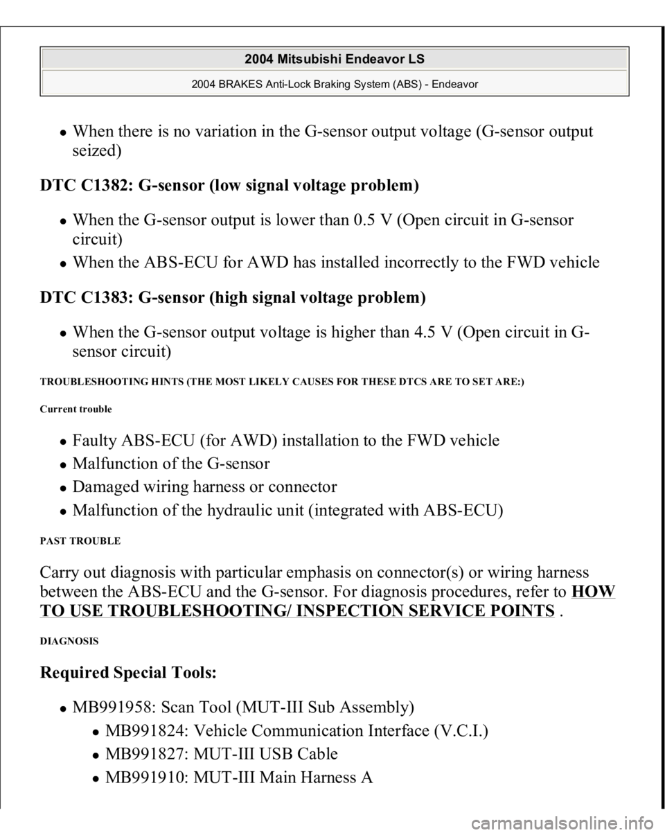
When there is no variation in the G-sensor output voltage (G-sensor output
seized)
DTC C1382: G-sensor (low signal voltage problem) When the G-sensor output is lower than 0.5 V (Open circuit in G-sensor
circuit) When the ABS-ECU for AWD has installed incorrectly to the FWD vehicle
DTC C1383: G-sensor (high signal voltage problem) When the G-sensor output voltage is higher than 4.5 V (Open circuit in G-
sensor circuit)
TROUBLESHOOTING HINTS (THE MOST LIKELY CAUSES FOR THESE DTCS ARE TO SET ARE:)
Current trouble
Faulty ABS-ECU (for AWD) installation to the FWD vehicle Malfunction of the G-sensor Damaged wiring harness or connector Malfunction of the hydraulic unit (integrated with ABS-ECU)
PAST TROUBLE Carry out diagnosis with particular emphasis on connector(s) or wiring harness
between the ABS-ECU and the G-sensor. For diagnosis procedures, refer to HOW TO USE TROUBLESHOOTING/ INSPECTION SERVICE POINTS
.
DIAGNOSIS Required Special Tools:
MB991958: Scan Tool (MUT-III Sub Assembly)
MB991824: Vehicle Communication Interface (V.C.I.) MB991827: MUT-III USB Cable MB991910: MUT-III Main Harness A
2004 Mitsubishi Endeavor LS
2004 BRAKES Anti-Lock Braking System (ABS) - Endeavor