Page 3572 of 3870

MITSUBISHI
3.8L V6 - SOHC - Endeavor & Galant
MANUFACTURER'S SUGGESTED SCHEDULED MAINTENANCE Manufacturer recommends the belt be replaced every 60,000 miles except in
California, Massachusetts and Vermont. In California, Massachusetts and Vermont,
timing belt replacement is recommended, but not required, at 60,000 miles. In these
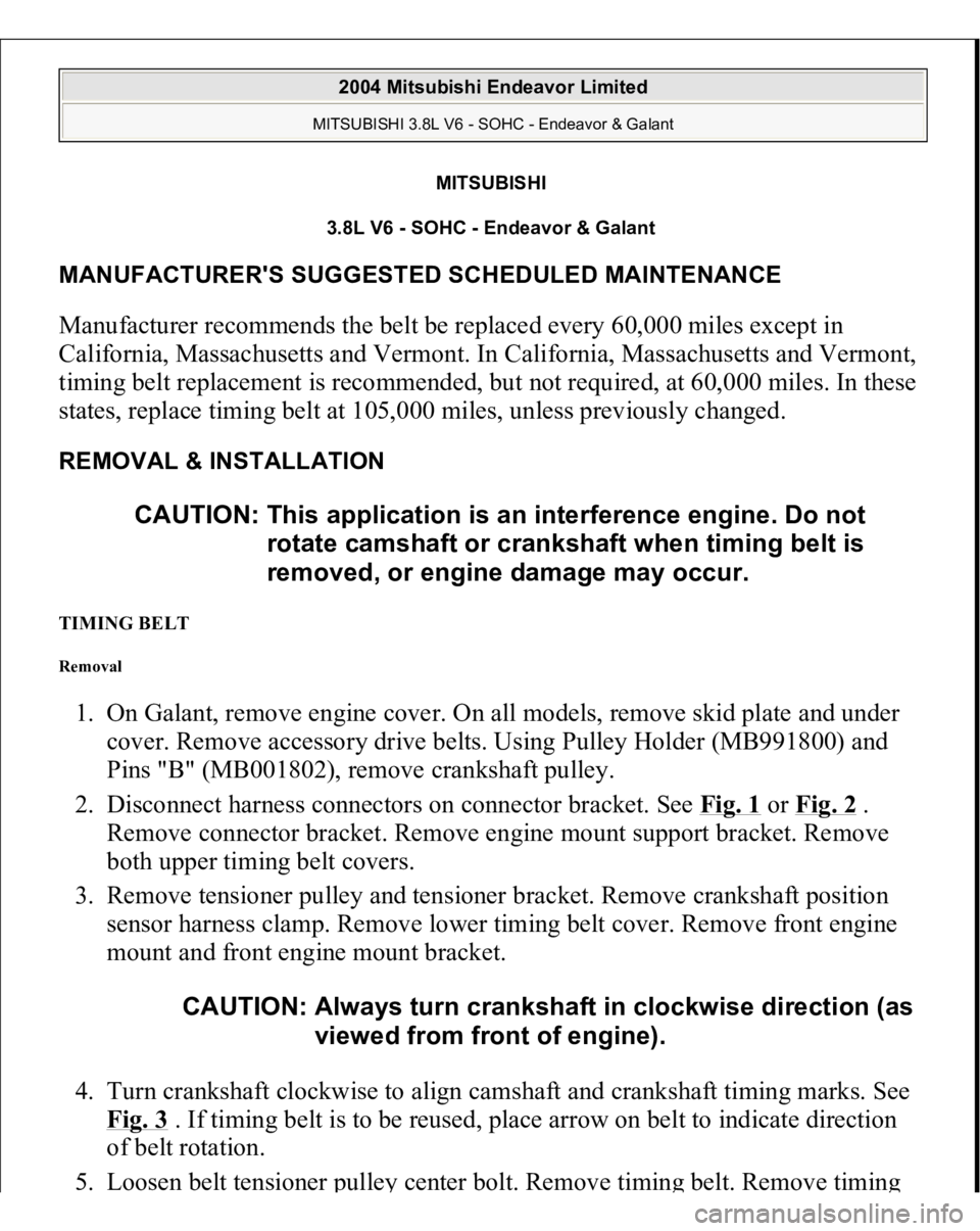
states, replace timing belt at 105,000 miles, unless previously changed. REMOVAL & INSTALLATION TIMING BELT Removal 1. On Galant, remove engine cover. On all models, remove skid plate and under
cover. Remove accessory drive belts. Using Pulley Holder (MB991800) and
Pins "B" (MB001802), remove crankshaft pulley.
2. Disconnect harness connectors on connector bracket. See Fig. 1
or Fig. 2
.
Remove connector bracket. Remove engine mount support bracket. Remove
both upper timing belt covers.
3. Remove tensioner pulley and tensioner bracket. Remove crankshaft position
sensor harness clamp. Remove lower timing belt cover. Remove front engine
mount and front engine mount bracket.
4. Turn crankshaft clockwise to align camshaft and crankshaft timing marks. See
Fig. 3
. If timing belt is to be reused, place arrow on belt to indicate direction
of belt rotation.
5. Loosen belt tensioner
pulle
y center bolt. Remove timin
g belt. Remove timin
g CAUTION: This application is an interference engine. Do not
rotate camshaft or crankshaft when timing belt is
removed, or engine damage may occur.
CAUTION: Always turn crankshaft in clockwise direction (as
viewed from front of engine).
2004 Mitsubishi Endeavor Limited MITSUBISHI 3.8L V6 - SOHC - Endeavor & Galant
2004 Mitsubishi Endeavor Limited MITSUBISHI 3.8L V6 - SOHC - Endeavor & Galant
Page 3694 of 3870

Fig. 58: Inspecting Harness Connector
Courtesy of MITSUBISHI MOTOR SALES OF AMERICA.
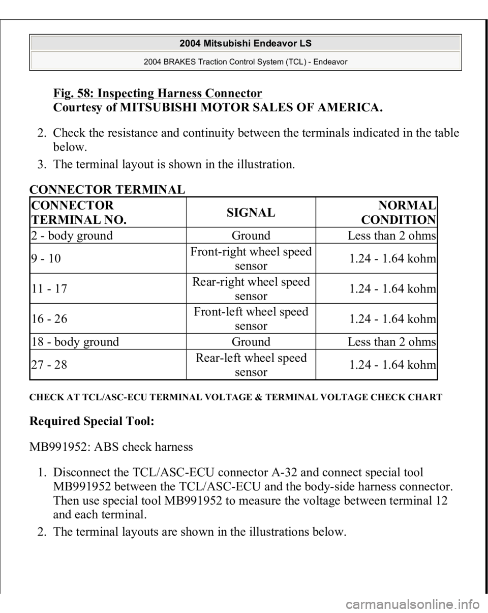
2. Check the resistance and continuity between the terminals indicated in the table
below.
3. The terminal layout is shown in the illustration.
CONNECTOR TERMINAL
CHECK AT TCL/ASC-ECU TERMINAL VOLTAGE & TERMINAL VOLTAGE CHECK CHART Required Special Tool:
MB991952: ABS check harness
1. Disconnect the TCL/ASC-ECU connector A-32 and connect special tool
MB991952 between the TCL/ASC-ECU and the body-side harness connector.
Then use special tool MB991952 to measure the voltage between terminal 12
and each terminal.
2. The terminal la
youts are shown in the illustrations below.
CONNECTOR
TERMINAL NO.
SIGNAL
NORMAL
CONDITION
2 - body ground
Ground
Less than 2 ohms
9 - 10
Front-right wheel speed
sensor
1.24 - 1.64 kohm
11 - 17
Rear-right wheel speed
sensor
1.24 - 1.64 kohm
16 - 26
Front-left wheel speed
sensor
1.24 - 1.64 kohm
18 - body ground
Ground
Less than 2 ohms
27 - 28
Rear-left wheel speed
sensor
1.24 - 1.64 kohm
2004 Mitsubishi Endeavor LS
2004 BRAKES Traction Control System (TCL) - Endeavor
Page 3698 of 3870
Fig. 61: Checking Resistance And Continuity
Courtesy of MITSUBISHI MOTOR SALES OF AMERICA.
CONNECTOR TERMINAL
SPECIAL TOOLS CONNECTOR
TERMINAL NO.
SIGNAL
NORMAL
CONDITION
6 - 7
Rear-left wheel speed
sensor
1.24 - 1.64 kohm
8 - 9
Rear-right wheel speed
sensor
1.24 - 1.64 kohm
12 - body ground
Ground
Less than 2 ohms
21 - 30
Front-right wheel speed
sensor
1.24 - 1.64 kohm
22 - 31
Front-left wheel speed
sensor
1.24 - 1.64 kohm
34 - body ground
Ground
Less than 2 ohms
2004 Mitsubishi Endeavor LS
2004 BRAKES Traction Control System (TCL) - Endeavor
Page 3705 of 3870

2. Turn the ignition switch to the "ON" position.
3. Use scan tool MB991958 to check the actuator test.
Item 09: Engine TCL Drive.
When the accelerator pedal is depressed at the same time that the
button for actuator test item 09 displayed on scan tool MB991958 is
pressed, the system prevents the engine speed from rising for three
seconds.
4. Turn the ignition switch to the "LOCK" (OFF) position.
5. Disconnect scan tool MB991958.
6. If defective, repair it. (Refer to TCL DIAGNOSIS
- SYMPTOM
PROCEDURE
, TRACTION CONTROL SYSTEM (TCL) DIAGNOSIS
).
TCL SWITCH CHECK 1. Remove the TCL switch. (Refer to TCL SWITCH
).
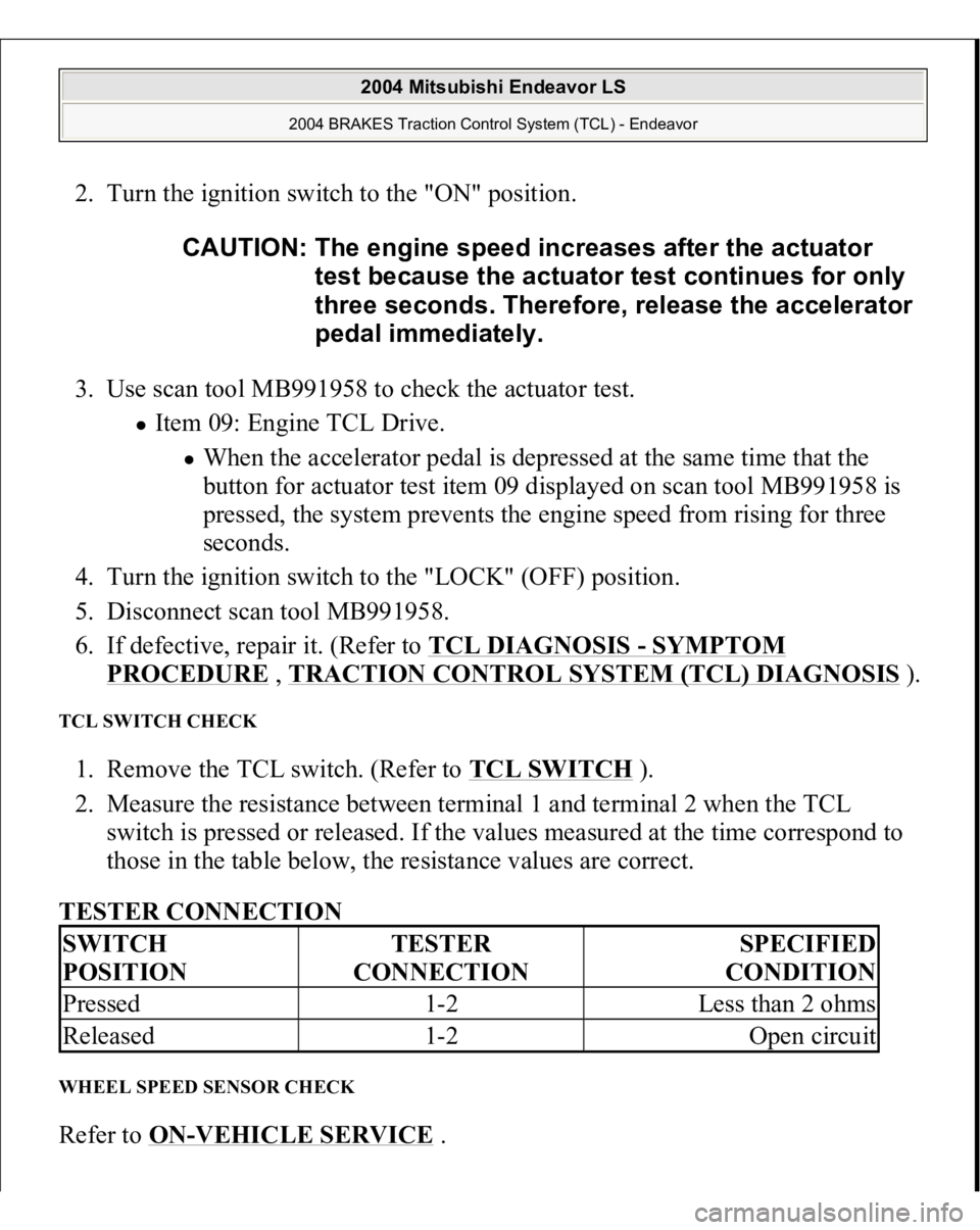
2. Measure the resistance between terminal 1 and terminal 2 when the TCL
switch is pressed or released. If the values measured at the time correspond to
those in the table below, the resistance values are correct.
TESTER CONNECTION
WHEEL SPEED SENSOR CHECK Refer to ON
-VEHICLE SERVICE
. CAUTION: The engine speed increases after the actuator
test because the actuator test continues for only
three seconds. Therefore, release the accelerator
pedal immediately.
SWITCH
POSITION
TESTER
CONNECTION
SPECIFIED
CONDITION
Pressed
1-2
Less than 2 ohms
Released
1-2
Open circuit
2004 Mitsubishi Endeavor LS
2004 BRAKES Traction Control System (TCL) - Endeavor
Page 3707 of 3870
Fig. 68: Removing & Installing TCL Components
Courtesy of MITSUBISHI MOTOR SALES OF AMERICA.
WHEEL SPEED SENSOR REMOVAL AND INSTALLATION Refer to WHEEL SPEED SENSOR
.
ABS/TCL-ECU REMOVAL AND INSTALLATION Replace the hydraulic unit (integrated with ABS/TCL-ECU < FWD > or TCL/ASC-
ECU < AWD >
). (Refer to HYDRAULIC UNIT
).
2004 Mitsubishi Endeavor LS
2004 BRAKES Traction Control System (TCL) - Endeavor