Page 165 of 3870
Fig. 97: Checking G
-Sensor Connector C
-23
Courtesy of MITSUBISHI MOTOR SALES OF AMERICA.
Check the connectors, for loose, corroded or damaged terminals, or terminals
2004 Mitsubishi Endeavor LS
2004 BRAKES Anti-Lock Braking System (ABS) - Endeavor
Page 166 of 3870
pushed back in the connector.
Q: Are the connectors and terminals in good condition?
YES: Go to Step 10.
NO: Repair or replace the damaged component(s). Then go to Step 13 .
STEP 10. Check the following harness wires.
The wire between ABS-ECU connector A-02 (terminal 8) and G-sensor
connector
C-23
(terminal 3
)
2004 Mitsubishi Endeavor LS
2004 BRAKES Anti-Lock Braking System (ABS) - Endeavor
Page 168 of 3870
Fig. 99: Checking G
-Sensor Connector C
-23
Courtesy of MITSUBISHI MOTOR SALES OF AMERICA.
The wire between AB
S-ECU connector A-02
(terminal 15
) and G-sensor
2004 Mitsubishi Endeavor LS
2004 BRAKES Anti-Lock Braking System (ABS) - Endeavor
Page 169 of 3870
connector C-23 (terminal 2)
Q: Is any harness wire damaged?
YES: Repair the harness wire. Then go to Step 13 .
NO: Go to Step 11.
STEP 11. Recheck for diagnostic trouble code after the G-sensor is
replaced.
Replace the G-sensor, and check whether DTC C1381, C1382 or C1383 is
reset.
1. Replace the G-sensor.
2. Connect scan tool MB991958 to the data link connec
tor. CAUTION: To prevent damage to scan tool MB991958,
always turn the ignition switch to the
"LOCK" (OFF) position before connecting or
disconnecting scan tool MB991958.
2004 Mitsubishi Endeavor LS
2004 BRAKES Anti-Lock Braking System (ABS) - Endeavor
Page 247 of 3870
Fig. 146: Identifying Special Tools (2 Of 2)
Courtesy of MITSUBISHI MOTOR SALES OF AMERICA.
ON-VEHICLE SERVICE ABS SENSOR OUTPUT VOLTAGE MEASUREMENT Required Special Tool:
MB991219: Inspection Harness
1. Release the parking brake and lift up the vehicle.
2. Disconnect the ABS-ECU connector A-02, and then use special tool
MB991219 to measure the out
put volta
ge at the harness side connector.
NOTE: For vehicles with ASC, refer to WHEEL SPEED SENSOR
OUTPUT VOLTAGE MEASUREMENT
.
2004 Mitsubishi Endeavor LS
2004 BRAKES Anti-Lock Braking System (ABS) - Endeavor
Page 250 of 3870
3. Manually turn the wheel to be measured 1/2 to 1 turn/second. Measure the
output voltage with a voltmeter or oscilloscope.
Output voltage:
Minimal voltmeter reading: 42 mV Maximum voltmeter reading: 300 mV Minimal oscilloscope reading: 120 mV Maximum oscillosco
pe readin
g: 600 mV NOTE: Check the connection of the sensor harness and
connector before using the oscilloscope.
2004 Mitsubishi Endeavor LS
2004 BRAKES Anti-Lock Braking System (ABS) - Endeavor
Page 252 of 3870

Fig. 149: Identifying Output Voltage Grap
h
Courtesy of MITSUBISHI MOTOR SALES OF AMERICA.
Probable causes of low output voltage
ABS sensor pole piece-to-ABS rotor clearance too large Faulty ABS sensor
4. To observe the waveform with an oscilloscope:
Front Wheels: Shift into "D" range and drive the wheels. Rear Wheels: Turn the wheels manually at a constant speed
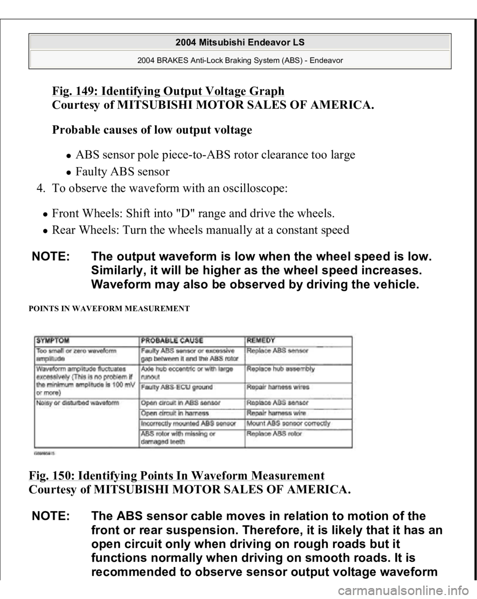
POINTS IN WAVEFORM MEASUREMENT Fig. 150: Identifying Points In Waveform Measurement
Courtesy of MITSUBISHI MOTOR SALES OF AMERICA. NOTE: The output waveform is low when the wheel speed is low.
Similarly, it will be higher as the wheel speed increases.
Waveform may also be observed by driving the vehicle.
NOTE: The ABS sensor cable moves in relation to motion of the
front or rear suspension. Therefore, it is likely that it has an
open circuit only when driving on rough roads but it
functions normally when driving on smooth roads. It is
recommended to observe sensor output voltage waveform
2004 Mitsubishi Endeavor LS
2004 BRAKES Anti-Lock Braking System (ABS) - Endeavor
Page 262 of 3870
Fig. 157: Identifying Brake Tube Connection
Courtesy of MITSUBISHI MOTOR SALES OF AMERICA.
WHEEL SPEED SENSOR REMOVAL AND INSTALLATION
2004 Mitsubishi Endeavor LS
2004 BRAKES Anti-Lock Braking System (ABS) - Endeavor