2004 MITSUBISHI ENDEAVOR sensor
[x] Cancel search: sensorPage 415 of 3870
between SRS ECU and seat slide sensor. Go to next step.
5. Erase, then retrieve DTCs. If DTC B1506 is retrieved, go to step 1 . If DTC
B1506 is not retrieved, system is normal at this time.
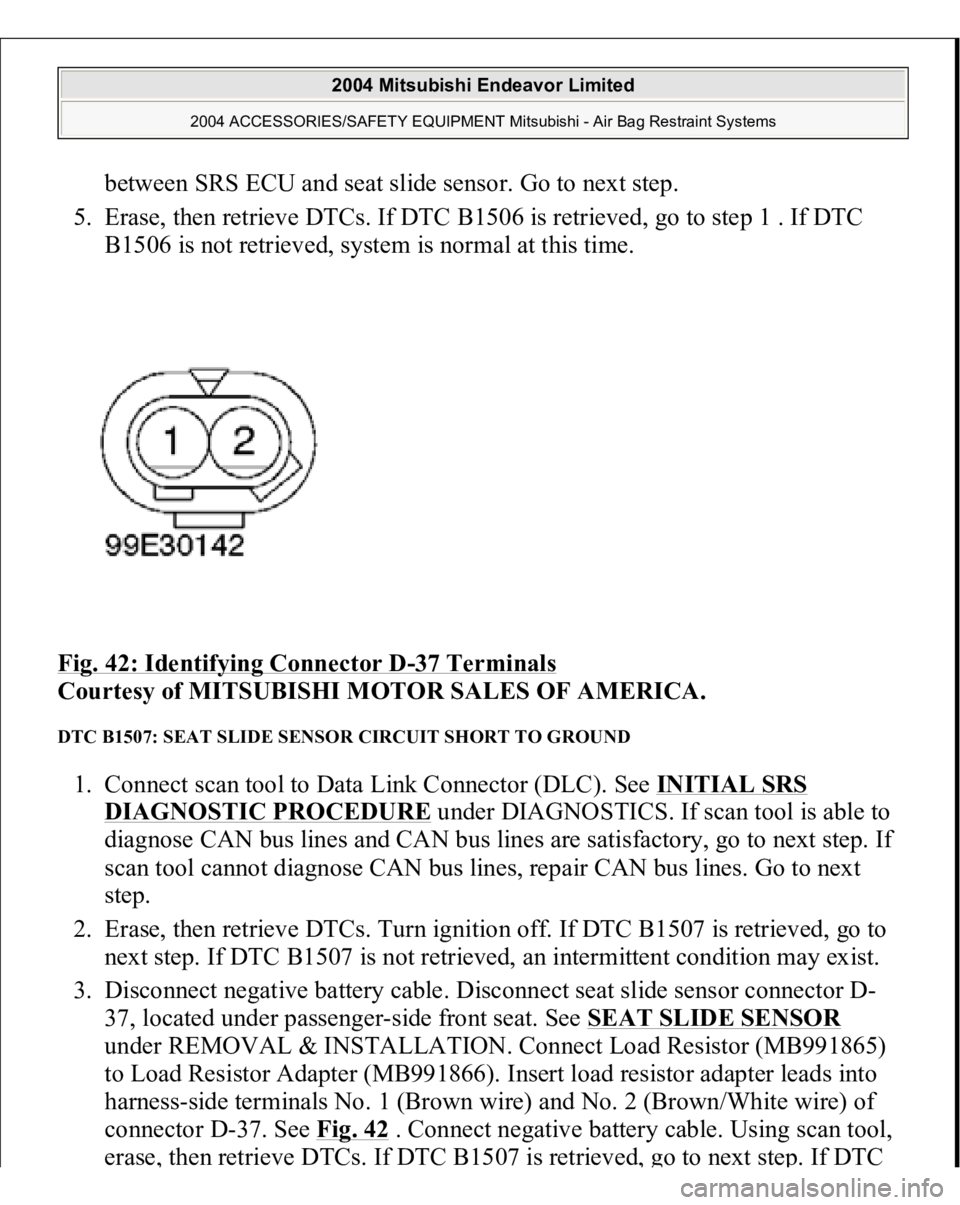
Fig. 42: Identifying Connector D
-37 Terminals
Courtesy of MITSUBISHI MOTOR SALES OF AMERICA.
DTC B1507: SEAT SLIDE SENSOR CIRCUIT SHORT TO GROUND 1. Connect scan tool to Data Link Connector (DLC). See INITIAL SRS
DIAGNOSTIC PROCEDURE
under DIAGNOSTICS. If scan tool is able to
diagnose CAN bus lines and CAN bus lines are satisfactory, go to next step. If
scan tool cannot diagnose CAN bus lines, repair CAN bus lines. Go to next
step.
2. Erase, then retrieve DTCs. Turn ignition off. If DTC B1507 is retrieved, go to
next step. If DTC B1507 is not retrieved, an intermittent condition may exist.
3. Disconnect negative battery cable. Disconnect seat slide sensor connector D-
37, located under passenger-side front seat. See SEAT SLIDE SENSOR
under REMOVAL & INSTALLATION. Connect Load Resistor (MB991865)
to Load Resistor Adapter (MB991866). Insert load resistor adapter leads into
harness-side terminals No. 1 (Brown wire) and No. 2 (Brown/White wire) of
connector D-37. See Fig. 42
. Connect negative battery cable. Using scan tool,
erase
, then retrieve DTCs. If DTC B1507 is retrieved
, go to next ste
p. If DTC
2004 Mitsubishi Endeavor Limited
2004 ACCESSORIES/SAFETY EQUIPMENT Mitsubishi - Air Bag Restraint Systems
Page 416 of 3870
B1507 is not retrieved, replace seat slide sensor. Go to step 5 .
4. Disconnect SRS ECU connector C-40. See SRS ELECTRONIC CONTROL UNIT (SRS ECU)
under REMOVAL & INSTALLATION. See Fig. 30
.
Remove load resistor and load resistor adapter from connector D-37. Measure
resistance between ground and SRS ECU connector C-40, terminal No. 2
(Brown wire). See Fig. 33
. Measure resistance between ground and SRS ECU
connector C-40, terminal No. 1 (Brown/White wire). If resistance is infinite at
both terminals, reconnect SRS components. Erase, then retrieve DTCs. If DTC
B1507 is retrieved, replace SRS ECU. If resistance is not infinite at both
terminals, replace wire harness between SRS ECU and seat slide sensor. Go to
next step.
5. Erase, then retrieve DTCs. If DTC B1507 is retrieved, go to step 1 . If DTC
B1507 is not retrieved, system is normal at this time.
DTC B1508: SEAT SLIDE SENSOR CIRCUIT SHORT TO VOLTAGE 1. Connect scan tool to Data Link Connector (DLC). See INITIAL SRS
DIAGNOSTIC PROCEDURE
under DIAGNOSTICS. If scan tool is able to
diagnose CAN bus lines and CAN bus lines are satisfactory, go to next step. If
scan tool cannot diagnose CAN bus lines, repair CAN bus lines. Go to next
step.
2. Erase, then retrieve DTCs. Turn ignition off. If DTC B1508 is retrieved, go to
next step. If DTC B1508 is not retrieved, an intermittent condition may exist.
3. Disconnect negative battery cable. Disconnect seat slide sensor connector D-
37, located under passenger-side front seat. See SEAT SLIDE SENSOR
under REMOVAL & INSTALLATION. Connect Load Resistor (MB991865)
to Load Resistor Adapter (MB991866). Insert load resistor adapter leads into
harness-side terminals No. 1 (Brown wire) and No. 2 (Brown/White wire) of
connector D-37. See Fig. 42
. Connect negative battery cable. Using scan tool,
erase, then retrieve DTCs. If DTC B1508 is retrieved, go to next step. If DTC
B1508 is not retrieved, replace seat slide sensor. Go to step 5 .
4. Disconnect SRS ECU connector C-40. See SRS ELECTRONIC CONTROL
UNIT (SRS ECU)
under REMOVAL & INSTALLATION. See Fig. 30
.
Remove load resistor and load resistor adapter from connector D-37. Measure
volta
ge between
ground and SRS ECU connector
C-40, terminal No. 2
(Brown
2004 Mitsubishi Endeavor Limited
2004 ACCESSORIES/SAFETY EQUIPMENT Mitsubishi - Air Bag Restraint Systems
Page 417 of 3870
wire). See Fig. 33
. Measure voltage between ground and SRS ECU connector
C-40, terminal No. 1 (Brown/White wire). If zero volt is measured at both
terminals, reconnect SRS components. Erase, then retrieve DTCs. If DTC
B1508 is retrieved, replace SRS ECU. If voltage is measured at either terminal,
replace wire harness between SRS ECU and seat slide sensor. Go to next step.
5. Erase, then retrieve DTCs. If DTC B1508 is retrieved, go to step 1 . If DTC
B1508 is not retrieved, system is normal at this time.
DTC B1509: INCORRECT SRS ECU 1. Connect scan tool to Data Link Connector (DLC). See INITIAL SRS
DIAGNOSTIC PROCEDURE
under DIAGNOSTICS. If scan tool is able to
diagnose CAN bus lines and CAN bus lines are satisfactory, go to next step. If
scan tool cannot diagnose CAN bus lines, repair CAN bus lines. Go to next
step.
2. Erase, then retrieve DTCs. If DTC B1509 is retrieved, replace SRS ECU. See
SRS ELECTRONIC CONTROL UNIT (SRS ECU)
under REMOVAL &
INSTALLATION. If DTC B1509 is not retrieved, an intermittent condition
may exist.
DTC B1519: SRS ECU CONNECTOR LOCK MALFUNCTION 1. Connect scan tool to Data Link Connector (DLC). See INITIAL SRS
DIAGNOSTIC PROCEDURE
under DIAGNOSTICS. If scan tool is able to
diagnose CAN bus lines and CAN bus lines are satisfactory, go to next step. If
scan tool cannot diagnose CAN bus lines, repair CAN bus lines. Go to next
step.
2. Erase, then retrieve DTCs. Turn ignition off. If DTC B1519 is retrieved, go to
next step. If DTC B1519 is not retrieved, an intermittent condition may exist.
3. Inspect SRS ECU connectors C-25, C-26 and C-40. See SRS ELECTRONIC
CONTROL UNIT (SRS ECU)
under REMOVAL & INSTALLATION. See
Fig. 30
. If connectors are connected properly, go to next step. If connectors
are not connected properly, reconnect properly. Go to step 5 .
4. Inspect and ensure lock contacts on SRS ECU connectors C-25, C-26 and C-40
are functioning properly and are not damaged. If connectors are not okay,
re
place wirin
g harness. Go to next ste
p. If connec
tors are oka
y, erase, then
2004 Mitsubishi Endeavor Limited
2004 ACCESSORIES/SAFETY EQUIPMENT Mitsubishi - Air Bag Restraint Systems
Page 438 of 3870
DIAGNOSTIC PROCEDURE
under DIAGNOSTICS. If scan tool is able to
diagnose CAN bus lines and CAN bus lines are satisfactory, go to next step. If
scan tool cannot diagnose CAN bus lines, repair CAN bus lines. Go to next
step.
2. Erase, then retrieve DTCs. If DTC B1541 is retrieved, replace front seat slide
adjuster. If DTC B1541 is not retrieved, an intermittent condition may exist.
DTC B1542: OCCUPANT CLASSIFICATION SENSOR S1 MALFUNCTION 1. Connect scan tool to Data Link Connector (DLC). See INITIAL SRS
DIAGNOSTIC PROCEDURE
under DIAGNOSTICS. If scan tool is able to
diagnose CAN bus lines and CAN bus lines are satisfactory, go to next step. If
scan tool cannot diagnose CAN bus lines, repair CAN bus lines. Go to next
step.
2. Erase, then retrieve DTCs. If DTC B1542 is retrieved, replace front seat slide
adjuster. If DTC B1542 is not retrieved, an intermittent condition may exist.
DTC B1543: OCCUPANT CLASSIFICATION SENSOR S2 MALFUNCTION 1. Connect scan tool to Data Link Connector (DLC). See INITIAL SRS
DIAGNOSTIC PROCEDURE
under DIAGNOSTICS. If scan tool is able to
diagnose CAN bus lines and CAN bus lines are satisfactory, go to next step. If
scan tool cannot diagnose CAN bus lines, repair CAN bus lines. Go to next
step.
2. Erase, then retrieve DTCs. If DTC B1543 is retrieved, replace front seat slide
adjuster. If DTC B1543 is not retrieved, an intermittent condition may exist.
DTC B1545: OCCUPANT CLASSIFICATION ECU COMMUNICATION ERROR 1. Connect scan tool to Data Link Connector (DLC). See INITIAL SRS
DIAGNOSTIC PROCEDURE
under DIAGNOSTICS. If scan tool is able to
diagnose CAN bus lines and CAN bus lines are satisfactory, go to next step. If
scan tool cannot diagnose CAN bus lines, repair CAN bus lines. Go to next
step.
2. Erase, then retrieve DTCs. Turn ignition off. If DTC B1545 is retrieved, go to
next step. If DTC B1545 is not retrieved, an intermittent condition may exist.
3.
Disconnect occupant classification ECU connector D
-38, located under
2004 Mitsubishi Endeavor Limited
2004 ACCESSORIES/SAFETY EQUIPMENT Mitsubishi - Air Bag Restraint Systems
Page 443 of 3870
diagnose CAN bus lines and CAN bus lines are satisfactory, go to next step. If
scan tool cannot diagnose CAN bus lines, repair CAN bus lines. Go to next
step.
2. Erase, then retrieve DTCs. If DTC B1555 is retrieved, replace SRS ECU. See
SRS ELECTRONIC CONTROL UNIT (SRS ECU)
under REMOVAL &
INSTALLATION. If DTC B1555 is not retrieved, an intermittent condition
may exist.
DTC B1556: SEAT SLIDE SENSOR MALFUNCTION 1. Connect scan tool to Data Link Connector (DLC). See INITIAL SRS
DIAGNOSTIC PROCEDURE
under DIAGNOSTICS. If scan tool is able to
diagnose CAN bus lines and CAN bus lines are satisfactory, go to next step. If
scan tool cannot diagnose CAN bus lines, repair CAN bus lines. Go to next
step.
2. Erase, then retrieve DTCs. Turn ignition off. If DTC B1556 is retrieved, go to
next step. If DTC B1556 is not retrieved, an intermittent condition may exist.
3. Replace seat slide sensor. See SEAT SLIDE SENSOR
under REMOVAL &
INSTALLATION. Check for DTCs. If DTC B1556 is retrieved, replace SRS
ECU. See SRS ELECTRONIC CONTROL UNIT (SRS ECU)
under
REMOVAL & INSTALLATION. If DTC B1556 is not retrieved, procedure is
complete.
DTCB1557: SRS ECU ASIC 1. Connect scan tool to Data Link Connector (DLC). See INITIAL SRS
DIAGNOSTIC PROCEDURE
under DIAGNOSTICS. If scan tool is able to
diagnose CAN bus lines and CAN bus lines are satisfactory, go to next step. If
scan tool cannot diagnose CAN bus lines, repair CAN bus lines. Go to next
step.
2. Erase, then retrieve DTCs. If DTC B1557 is retrieved, replace SRS ECU. See
SRS ELECTRONIC CONTROL UNIT (SRS ECU)
under REMOVAL &
INSTALLATION. If DTC B1557 is not retrieved, an intermittent condition
may exist.
DTCB1558: OCCUPANT CLASSIFICATION ECU ID CORD MALFUNCTION
2004 Mitsubishi Endeavor Limited
2004 ACCESSORIES/SAFETY EQUIPMENT Mitsubishi - Air Bag Restraint Systems
Page 444 of 3870
1. Connect scan tool to Data Link Connector (DLC). See INITIAL SRS
DIAGNOSTIC PROCEDURE
under DIAGNOSTICS. If scan tool is able to
diagnose CAN bus lines and CAN bus lines are satisfactory, go to next step. If
scan tool cannot diagnose CAN bus lines, repair CAN bus lines. Go to next
step.
2. Erase, then retrieve DTCs. If DTC B1558 is retrieved, replace seat slide sensor.
See SEAT SLIDE SENSOR
under REMOVAL & INSTALLATION. If DTC
B1558 is not retrieved, an intermittent condition may exist.
DTC U1073: BUS OFF 1. Connect scan tool to Data Link Connector (DLC). See INITIAL SRS
DIAGNOSTIC PROCEDURE
under DIAGNOSTICS. If scan tool is able to
diagnose CAN bus lines and CAN bus lines are satisfactory, go to next step. If
scan tool cannot diagnose CAN bus lines, repair CAN bus lines. Go to next
step.
2. Erase, then retrieve DTCs. If scan tool retrieves DTC U1073, replace A/C
ECU. If scan tool does not retrieve DTC U1073, an intermittent condition may
exist.
COMPONENT TESTING OCCUPANT CLASSIFICATION SENSOR CALIBRATION (DUAL-STAGE AIR BAG SYSTEM) 1. Connect scan tool to Data Link Connector (DLC). See INITIAL SRS
DIAGNOSTIC PROCEDURE
under DIAGNOSTICS. Go to next step.
2. Open and close passenger-side front door 5 times hard to remove friction. If
door does not open and close smoothly after the impact, hit front and rear sides
of seat back about 8 times each to remove friction. Go to next step.
3. Select INTERACTIVE DIAGNOSIS, then SPECIAL FUNCTION then SEAT
WEIGHT SENSOR ACCURACY CHECK on screen. Slide passenger-side
front seat to full forward position. Place a 66 pound weight (30 kg) in center of
passenger-side seat cushion. Repeat step2 . Touch OK button to perform
accuracy check.
4. If variance between sensor output and input levels is within 11 pounds (5 kg),
ACCURACY CHECK COMPLETION will be dis
played on screen. Go to ste
p
2004 Mitsubishi Endeavor Limited
2004 ACCESSORIES/SAFETY EQUIPMENT Mitsubishi - Air Bag Restraint Systems
Page 445 of 3870
6 . If ACCURACY CHECK COMPLETION is not displayed, go to next step.
5. If ABNORMAL CONDITION is displayed, press OK and go to calibration
screen. Remove weight from seat. Verify seat is installed correctly. If seat is
installed correctly, go to step 1 .
6. Remove weight from seat cushion. Move seat to rear most position. Repeat
step2 . Go to next step.
7. Select INTERACTIVE DIAGNOSIS, then SPECIAL FUNCTION then SEAT
WEIGHT SENSOR ACCURACY CHECK on screen. Place a 66 pound weight
(30 kg) in center of passenger-side seat cushion. Repeat step2 . Touch OK
button to perform accuracy check. Go to next step.
8. If variance between sensor output and input levels is within 11 pounds (5 kg),
ACCURACY CHECK COMPLETION will be displayed on screen.
Calibration is complete. If ACCURACY CHECK COMPLETION is not
displayed, go to next step.
9. Verify seat is installed correctly. Repeat step2 . Touch OK button. When
EXECUTION prompt is displayed, touch OK button. When calibration is
completed, screen will display ZERO CALIBRATION COMPLETED. If
calibration cannot be completed, an intermittent condition may exist.
FRONT IMPACT SENSOR (DUAL-STAGE AIR BAG SYSTEM) 1. Remove appropriate front impact sensor. See FRONT IMPACT SENSOR
under REMOVAL & INSTALLATION. Visually inspect front impact sensor
case, connectors and brackets for damage. If no damage is found, go to next
step. If damage is found, discard front impact sensor.
2. Measure resistance between terminals of front impact sensor. Resistance
should be 738-902 ohms. Measure resistance between front impact sensor
terminals and front impact sensor case. Resistance should be infinite. If
resistance is not as specified, replace front impact sensor.
WIRING DIAGRAMS
2004 Mitsubishi Endeavor Limited
2004 ACCESSORIES/SAFETY EQUIPMENT Mitsubishi - Air Bag Restraint Systems
Page 471 of 3870
Courtesy of MITSUBISHI MOTOR SALES OF AMERICA
.
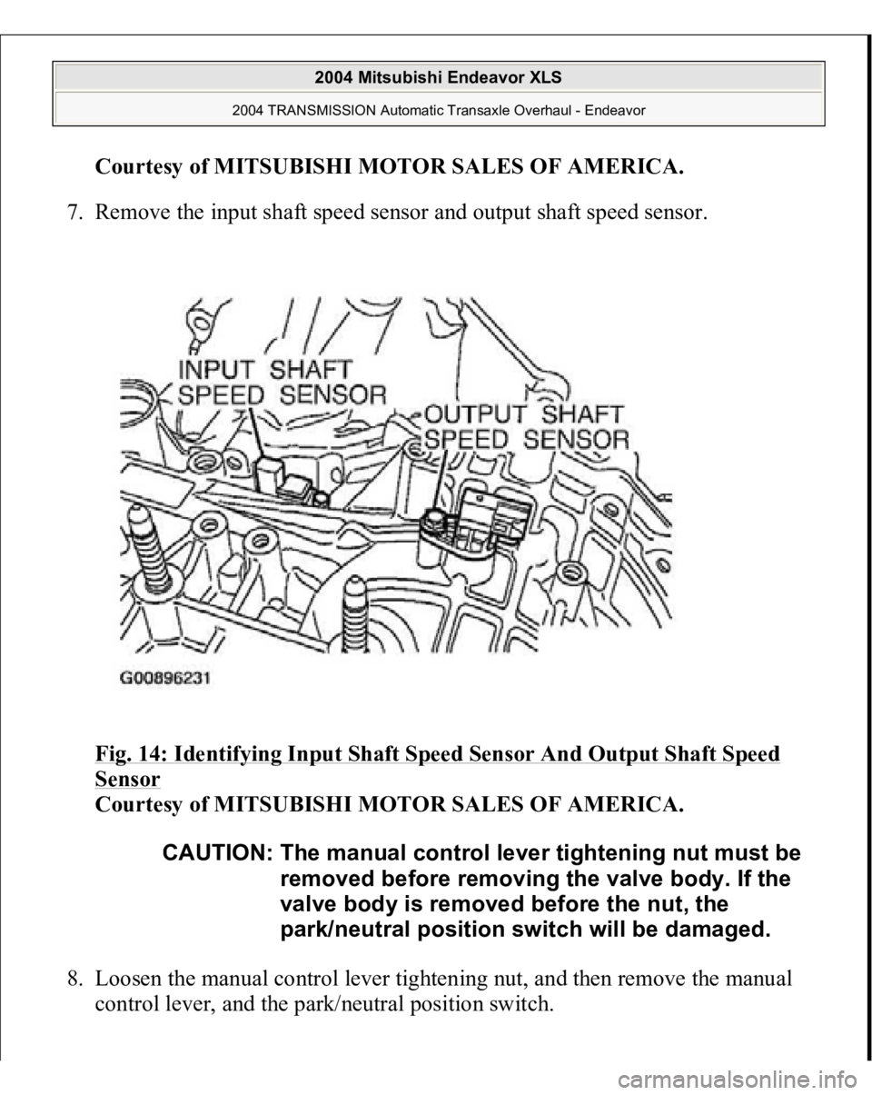
7. Remove the input shaft speed sensor and output shaft speed sensor.
Fig. 14: Identifying Input Shaft Speed Sensor And Output Shaft Speed
Sensor
Courtesy of MITSUBISHI MOTOR SALES OF AMERICA.
8. Loosen the manual control lever tightening nut, and then remove the manual
control lever, and the park/neutral position switch. CAUTION: The manual control lever tightening nut must be
removed before removing the valve body. If the
valve body is removed before the nut, the
park/neutral position switch will be damaged.
2004 Mitsubishi Endeavor XLS
2004 TRANSMISSION Automatic Transaxle Overhaul - Endeavor