2004 MITSUBISHI ENDEAVOR sensor
[x] Cancel search: sensorPage 363 of 3870
SHORT 1. Connect scan tool to Data Link Connector (DLC). See INITIAL SRS
DIAGNOSTIC PROCEDURE
under DIAGNOSTICS. If scan tool is able to
diagnose CAN bus lines and CAN bus lines are satisfactory, go to next step. If
scan tool cannot diagnose CAN bus lines, repair CAN bus lines. Go to next
step.
2. Erase, then retrieve DTCs. If DTC B1414 is retrieved, replace SRS ECU. See
SRS ELECTRONIC CONTROL UNIT (SRS ECU)
under REMOVAL &
INSTALLATION. If DTC B1414 is not retrieved, an intermittent condition
may exist.
DTC B1415: PASSENGER-SIDE AIR BAG MODULE FIRST-STAGE ACTIVATION CIRCUIT
SHORT 1. Connect scan tool to Data Link Connector (DLC). See INITIAL SRS
DIAGNOSTIC PROCEDURE
under DIAGNOSTICS. If scan tool is able to
diagnose CAN bus lines and CAN bus lines are satisfactory, go to next step. If
scan tool cannot diagnose CAN bus lines, repair CAN bus lines. Go to next
step.
2. Erase, then retrieve DTCs. If DTC B1415 is retrieved, replace SRS ECU. See
SRS ELECTRONIC CONTROL UNIT (SRS ECU)
under REMOVAL &
INSTALLATION. If DTC B1415 is not retrieved, an intermittent condition
may exist.
DTC B1416: FRONT IMPACT G SENSOR (LH) FAILURE 1. Connect scan tool to Data Link Connector (DLC). See INITIAL SRS
DIAGNOSTIC PROCEDURE
under DIAGNOSTICS. If scan tool is able to
diagnose CAN bus lines and CAN bus lines are satisfactory, go to next step. If
scan tool cannot diagnose CAN bus lines, repair CAN bus lines. Go to next
step.
2. Erase, then retrieve DTCs. If DTC B1416 is retrieved, go to next step. If DTC
B1416 is not retrieved, an intermittent condition may exist.
3. Replace driver-side front impact sensor. See FRONT IMPACT SENSOR
under REMOVAL & INSTALLATION. Reconnect SRS components. Erase,
then retrieve DTCs. If DTC B1416 is retrieved, re
place SRS ECU. See SRS
2004 Mitsubishi Endeavor Limited
2004 ACCESSORIES/SAFETY EQUIPMENT Mitsubishi - Air Bag Restraint Systems
Page 364 of 3870
ELECTRONIC CONTROL UNIT (SRS ECU)
under REMOVAL &
INSTALLATION. If DTC B1416 is not retrieved, system is normal at this
time.
DTC B1417: FRONT IMPACT SENSOR (LH) VOLTAGE ERROR 1. Connect scan tool to Data Link Connector (DLC). See INITIAL SRS
DIAGNOSTIC PROCEDURE
under DIAGNOSTICS. If scan tool is able to
diagnose CAN bus lines and CAN bus lines are satisfactory, go to next step. If
scan tool cannot diagnose CAN bus lines, repair CAN bus lines. Go to next
step.
2. Erase, then retrieve DTCs. If DTC B1417 is retrieved, go to next step. If DTC
B1417 is not retrieved, an intermittent condition may exist.
3. Disconnect negative battery terminal. Disconnect driver-side front impact
sensor connector A-21. See FRONT IMPACT SENSOR
under REMOVAL
& INSTALLATION. See Fig. 30
. Connect negative battery cable. Turn
ignition on. Measure voltage between ground and terminal No. 2 (Black/Blue
wire) of driver-side front impact sensor. See Fig. 34
. If voltage is 9 volts or
more, replace front impact sensor. Go to step 1 . If voltage is less than 9 volts,
go to next step.
4. Disconnect SRS ECU connector C-26. See SRS ELECTRONIC CONTROL
UNIT (SRS ECU)
under REMOVAL & INSTALLATION. Inspect
White/Blue wire between SRS ECU connector C-26, terminal No. 38 and front
impact sensor connector A-21, terminal No. 1 for an open or short circuit,
including connector C-31. Inspect Black/Blue wire between SRS ECU
connector C-26, terminal No. 39 and front impact sensor connector A-21,
terminal No. 2 for an open or short circuit, including connector C-31. If an
open or short circuit is found in either wire, replace wire harness between SRS
ECU and front impact sensor. Go to next step. If wires are okay, reconnect
SRS components. Erase, then retrieve DTCs. If DTC B1417 is retrieved,
replace SRS ECU. Go to next step.
5. Reconnect all SRS components. Activate air bag system. Using scan tool,
retrieve DTCs. If DTC B1417 is retrieved, go to step 1 . If DTC B1417 is not
retrieved, system is normal at this time.
DTC B1418: FRONT IMPACT SENSOR (LH) COMMUNICATION ERROR
2004 Mitsubishi Endeavor Limited
2004 ACCESSORIES/SAFETY EQUIPMENT Mitsubishi - Air Bag Restraint Systems
Page 365 of 3870
1. Connect scan tool to Data Link Connector (DLC). See INITIAL SRS
DIAGNOSTIC PROCEDURE
under DIAGNOSTICS. If scan tool is able to
diagnose CAN bus lines and CAN bus lines are satisfactory, go to next step. If
scan tool cannot diagnose CAN bus lines, repair CAN bus lines. Go to next
step.
2. Erase, then retrieve DTCs. If DTC B1418 is retrieved, go to next step. If DTC
B1418 is not retrieved, an intermittent condition may exist.
3. Disconnect negative battery cable. Replace driver-side front impact sensor with
passenger-side front impact sensor. See FRONT IMPACT SENSOR
under
REMOVAL & INSTALLATION. Connect negative battery cable. Erase, then
retrieve DTCs. If DTC B1408 or B1409 is retrieved, replace driver-side front
impact sensor. If DTC B1408 or B1409 is not retrieved, go to next step.
4. Disconnect SRS ECU connector C-26. See SRS ELECTRONIC CONTROL
UNIT (SRS ECU)
under REMOVAL & INSTALLATION. See Fig. 30
.
Inspect White/Blue wire between SRS ECU connector C-26, terminal No. 38
and front impact sensor connector A-23, terminal No. 1 for an open or short
circuit, including connector C-31. See Fig. 33
& Fig. 34
. Inspect Black/Blue
wire between SRS ECU connector C-26, terminal No. 39 and front impact
sensor connector A-23, terminal No. 2 for an open or short circuit, including
connector C-31. If an open or short circuit is found in either wire, replace wire
harness between SRS ECU and front impact sensor. Go to next step. If wires
are okay, reconnect SRS components. Erase, then retrieve DTCs. If DTC
B1418 is retrieved, replace SRS ECU. Go to next step.
5. Reconnect SRS components. Erase, then retrieve DTCs. If DTC B1418 is
retrieved, go to step 1 . If DTC B1418 is not retrieved, system is normal at this
time.
DTC B1419: FRONT IMPACT SENSOR (LH) COMMUNICATION IMPOSSIBLE 1. Connect scan tool to Data Link Connector (DLC). See INITIAL SRS
DIAGNOSTIC PROCEDURE
under DIAGNOSTICS. If scan tool is able to
diagnose CAN bus lines and CAN bus lines are satisfactory, go to next step. If
scan tool cannot diagnose CAN bus lines, repair CAN bus lines. Go to next
step.
2. Erase, then retrieve DTCs. If DTC B1419 is retrieved,
go to next ste
p. If DTC
2004 Mitsubishi Endeavor Limited
2004 ACCESSORIES/SAFETY EQUIPMENT Mitsubishi - Air Bag Restraint Systems
Page 366 of 3870
B1419 is not retrieved, an intermittent condition may exist.
3. Disconnect negative battery cable. Replace driver-side front impact sensor with
passenger-side front impact sensor. See FRONT IMPACT SENSOR
under
REMOVAL & INSTALLATION. Connect negative battery cable. Erase, then
retrieve DTCs. If DTC B1408 or B1409 is retrieved, replace driver-side front
impact sensor. If DTC B1408 or B1409 is not retrieved, go to next step.
4. Disconnect SRS ECU connector C-26. See SRS ELECTRONIC CONTROL
UNIT (SRS ECU)
under REMOVAL & INSTALLATION. See Fig. 30
.
Inspect White/Blue wire between SRS ECU connector C-26, terminal No. 38
and front impact sensor connector A-23, terminal No. 1 for an open or short
circuit, including connector C-31. See Fig. 33
& Fig. 34
. Inspect Black/Blue
wire between SRS ECU connector C-26, terminal No. 39 and front impact
sensor connector A-23, terminal No. 2 for an open or short circuit, including
connector C-31. If an open or short circuit is found in either wire, replace wire
harness between SRS ECU and front impact sensor. Go to next step. If wires
are okay, reconnect SRS components. Erase, then retrieve DTCs. If DTC
B1418 is retrieved, replace SRS ECU. Go to next step.
5. Reconnect SRS components. Erase, then retrieve DTCs. If DTC B1419 is
retrieved, go to step 1 . If DTC B1419 is not retrieved, system is normal at this
time.
DTC B1420: SIDE IMPACT AIR BAG MODULE (RH) SHORT CIRCUIT 1. Connect scan tool to Data Link Connector (DLC). See INITIAL SRS
DIAGNOSTIC PROCEDURE
under DIAGNOSTICS. If scan tool is able to
diagnose CAN bus lines and CAN bus lines are satisfactory, go to next step. If
scan tool cannot diagnose CAN bus lines, repair CAN bus lines. Go to next
step.
2. Erase, then retrieve DTCs. Turn ignition off. If DTC B1420 is retrieved, go to
next step. If DTC B1420 is not retrieved, an intermittent condition may exist.
3. Turn ignition on. If DTC B1519 is retrieved by scan tool, go to next step. If
DTC B1519 is not retrieved by scan tool, go to step 5 .
4. Inspect SRS ECU connector C-25. See SRS ELECTRONIC CONTROL
UNIT (SRS ECU)
under REMOVAL & INSTALLATION. See Fig. 30
. If
connector is connected correctl
y, go to next ste
p. If connector is not connected
2004 Mitsubishi Endeavor Limited
2004 ACCESSORIES/SAFETY EQUIPMENT Mitsubishi - Air Bag Restraint Systems
Page 371 of 3870
connector shorting bar using a cable tie. Measure resistance between ground
and SRS ECU connector C-25, terminal No. 58 (Yellow wire). See Fig. 33
.
Measure resistance between ground and terminal No. 57 (Yellow/Black wire).
If resistance is not infinite at both terminals, go to next step. If resistance is
infinite at both terminals, reconnect SRS components. Erase, then retrieve
DTCs. If DTC B1423 is retrieved, replace SRS ECU. Go to step 6 .
5. Replace wire harness between SRS ECU and passenger side impact air bag
module. Go to next step.
6. Reconnect all SRS components. Activate air bag system. Using scan tool,
retrieve DTCs. If DTC B1423 is retrieved, go to step 1 . If DTC B1423 is not
retrieved, system is normal at this time.
DTC B1424: SIDE IMPACT AIR BAG MODULE (RH) DRIVE CIRCUIT SHORTED 1. Connect scan tool to Data Link Connector (DLC). See INITIAL SRS
DIAGNOSTIC PROCEDURE
under DIAGNOSTICS. If scan tool is able to
diagnose CAN bus lines and CAN bus lines are satisfactory, go to next step. If
scan tool cannot diagnose CAN bus lines, repair CAN bus lines. Go to next
step.
2. Erase, then retrieve DTCs. If DTC B1424 is retrieved, replace SRS ECU. See
SRS ELECTRONIC CONTROL UNIT (SRS ECU)
under REMOVAL &
INSTALLATION. If DTC B1424 is not retrieved, an intermittent condition
may exist.
DTC B1425: SIDE IMPACT AIR BAG MODULE (RH) DRIVE CIRCUIT OPEN 1. Connect scan tool to Data Link Connector (DLC). See INITIAL SRS
DIAGNOSTIC PROCEDURE
under DIAGNOSTICS. If scan tool is able to
diagnose CAN bus lines and CAN bus lines are satisfactory, go to next step. If
scan tool cannot diagnose CAN bus lines, repair CAN bus lines. Go to next
step.
2. Erase, then retrieve DTCs. If DTC B1425 is retrieved, replace SRS ECU. See
SRS ELECTRONIC CONTROL UNIT (SRS ECU)
under REMOVAL &
INSTALLATION. If DTC B1425 is not retrieved, an intermittent condition
may exist.
DTC B1426: SIDE IMPACT SENSOR (RH) FAILURE
2004 Mitsubishi Endeavor Limited
2004 ACCESSORIES/SAFETY EQUIPMENT Mitsubishi - Air Bag Restraint Systems
Page 372 of 3870
1. Connect scan tool to Data Link Connector (DLC). See INITIAL SRS
DIAGNOSTIC PROCEDURE
under DIAGNOSTICS. If scan tool is able to
diagnose CAN bus lines and CAN bus lines are satisfactory, go to next step. If
scan tool cannot diagnose CAN bus lines, repair CAN bus lines.
2. Erase, then retrieve DTCs. If DTC B1426 is retrieved, go to next step. If DTC
B1426 is not retrieved, an intermittent condition may exist.
3. Replace passenger-side impact sensor. See FRONT IMPACT SENSOR
under REMOVAL & INSTALLATION. Reconnect SRS components. Erase,
then retrieve DTCs. If DTC B1426 is retrieved, replace SRS ECU. See SRS
ELECTRONIC CONTROL UNIT (SRS ECU)
under REMOVAL &
INSTALLATION. If DTC B1426 is not retrieved, system is normal at this
time.
DTC B1427: SIDE IMPACT SENSOR (RH) VOLTAGE ERROR 1. Connect scan tool to Data Link Connector (DLC). See INITIAL SRS
DIAGNOSTIC PROCEDURE
under DIAGNOSTICS. If scan tool is able to
diagnose CAN bus lines and CAN bus lines are satisfactory, go to next step. If
scan tool cannot diagnose CAN bus lines, repair CAN bus lines. Go to next
step.
2. Erase, then retrieve DTCs. Turn ignition off. If DTC B1427 is retrieved, go to
next step. If DTC B1427 is not retrieved, an intermittent condition may exist.
3. Disconnect negative battery cable. Disconnect passenger side impact sensor
connector D-33. See SEAT SLIDE SENSOR
under REMOVAL &
INSTALLATION. See Fig. 30
. Connect negative battery cable. Turn ignition
on. Measure voltage between ground and side impact sensor connector D-33,
terminal No. 2 (Black/Red wire). See Fig. 37
. If voltage is 9 volts or more,
replace side impact sensor. Go to step 6 . If voltage is less than 9 volts, go to
next step.
4. Disconnect negative battery cable. Disconnect SRS ECU connector C-25. See
SRS ELECTRONIC CONTROL UNIT (SRS ECU)
under REMOVAL &
INSTALLATION. Release SRS ECU connector shorting bar using a cable tie.
Measure resistance of Black/Red wire between SRS ECU connector C-25,
terminal No. 63 and side impact sensor connector D-33, terminal No. 2.
Measure resistance of White/Red wire between SRS ECU connector
C-25,
2004 Mitsubishi Endeavor Limited
2004 ACCESSORIES/SAFETY EQUIPMENT Mitsubishi - Air Bag Restraint Systems
Page 373 of 3870
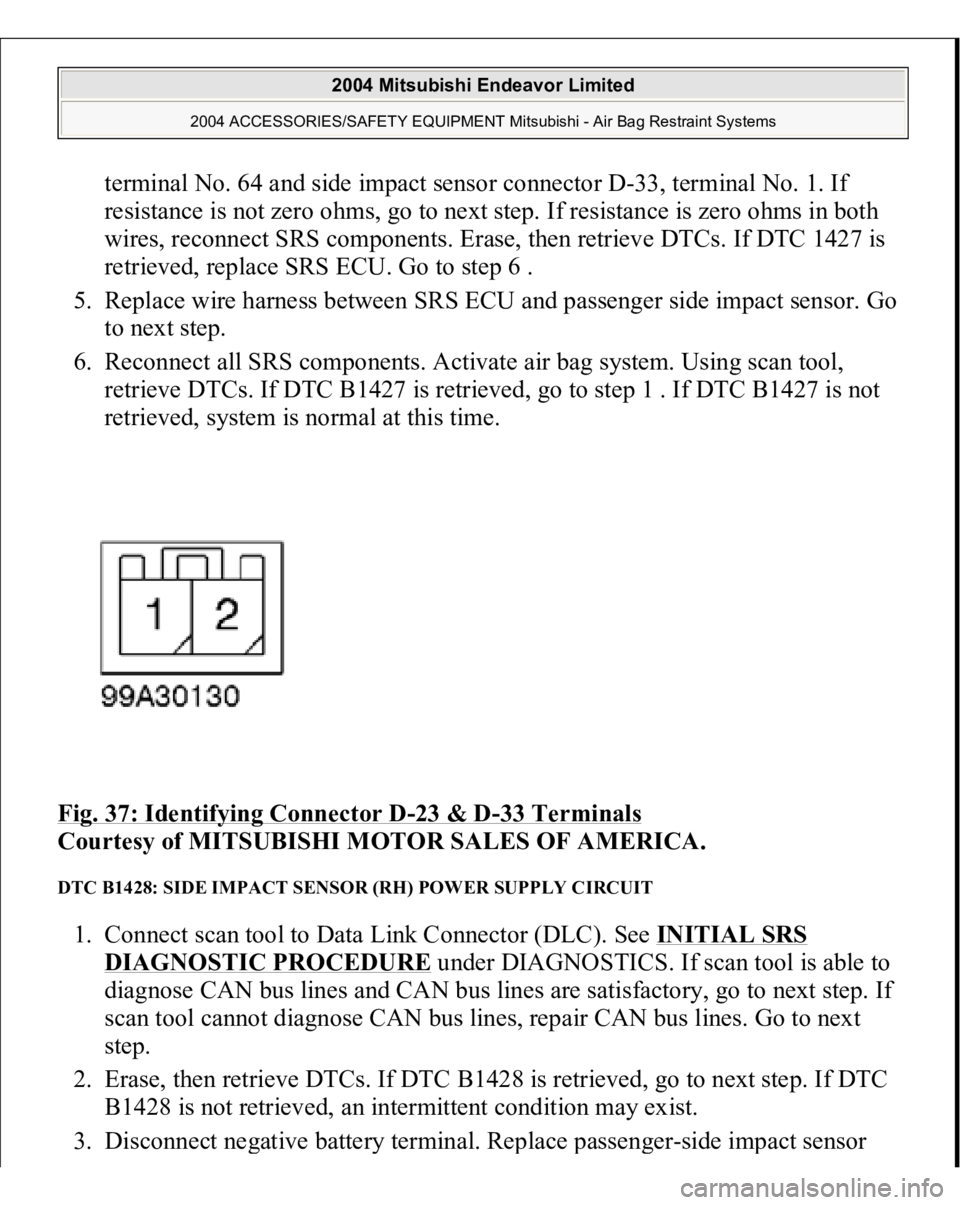
terminal No. 64 and side impact sensor connector D-33, terminal No. 1. If
resistance is not zero ohms, go to next step. If resistance is zero ohms in both
wires, reconnect SRS components. Erase, then retrieve DTCs. If DTC 1427 is
retrieved, replace SRS ECU. Go to step 6 .
5. Replace wire harness between SRS ECU and passenger side impact sensor. Go
to next step.
6. Reconnect all SRS components. Activate air bag system. Using scan tool,
retrieve DTCs. If DTC B1427 is retrieved, go to step 1 . If DTC B1427 is not
retrieved, system is normal at this time.
Fig. 37: Identifying Connector D
-23 & D
-33 Terminals
Courtesy of MITSUBISHI MOTOR SALES OF AMERICA.
DTC B1428: SIDE IMPACT SENSOR (RH) POWER SUPPLY CIRCUIT 1. Connect scan tool to Data Link Connector (DLC). See INITIAL SRS
DIAGNOSTIC PROCEDURE
under DIAGNOSTICS. If scan tool is able to
diagnose CAN bus lines and CAN bus lines are satisfactory, go to next step. If
scan tool cannot diagnose CAN bus lines, repair CAN bus lines. Go to next
step.
2. Erase, then retrieve DTCs. If DTC B1428 is retrieved, go to next step. If DTC
B1428 is not retrieved, an intermittent condition may exist.
3. Disconnect ne
gative batter
y terminal. Re
place
passen
ger-side im
pact sensor
2004 Mitsubishi Endeavor Limited
2004 ACCESSORIES/SAFETY EQUIPMENT Mitsubishi - Air Bag Restraint Systems
Page 374 of 3870
with driver-side impact sensor. See SIDE IMPACT SENSO
R under
REMOVAL & INSTALLATION. Connect negative battery cable. Erase, then
retrieve DTCs. If DTC B1438 or B1439 is retrieved, replace passenger-side
impact sensor. Go to step 5 . If DTC B1438 or B1439 is not retrieved, go to
next step.
4. Disconnect negative battery cable. Disconnect SRS ECU connector C-25. See
SRS ELECTRONIC CONTROL UNIT (SRS ECU)
under REMOVAL &
INSTALLATION. See Fig. 30
. Release SRS ECU connector shorting bar
using a cable tie. Inspect Black/Red wire between SRS ECU connector C-25,
terminal No. 63 and side impact sensor connector D-33, terminal No. 2 for an
open or short circuit. See Fig. 37 . Inspect White/Red wire between SRS ECU
connector C-25, terminal No. 64 and side impact sensor connector D-33,
terminal No. 1 for an open or short circuit. If an open or short circuit is not
found, reconnect SRS components. Erase, then retrieve DTCs. If DTC B1428
is retrieved, replace SRS ECU. Go to next step. If an open or short circuit is
found in either wire, replace wire harness between SRS ECU and side impact
sensor. Go to next step.
5. Reconnect all SRS components. Activate air bag system. Using scan tool,
retrieve DTCs. If DTC B1428 is retrieved, go to step 1 . If DTC B1428 is not
retrieved, system is normal at this time.
DTCB1429: FRONT IMPACT SENSOR (RH) COMMUNICATION IMPOSSIBLE 1. Connect scan tool to Data Link Connector (DLC). See INITIAL SRS
DIAGNOSTIC PROCEDURE
under DIAGNOSTICS. If scan tool is able to
diagnose CAN bus lines and CAN bus lines are satisfactory, go to next step. If
scan tool cannot diagnose CAN bus lines, repair CAN bus lines. Go to next
step.
2. Erase, then retrieve DTCs. If DTC B1428 is retrieved, go to next step. If DTC
B1428 is not retrieved, an intermittent condition may exist.
3. Disconnect negative battery terminal. Replace passenger-side impact sensor
with driver-side impact sensor. See SIDE IMPACT SENSOR
under
REMOVAL & INSTALLATION. Connect negative battery cable. Erase, then
retrieve DTCs. If DTC B1438 or B1439 is retrieved, replace passenger-side
impact sensor. Go to step 5 . If DTC B1438 or B1439 is not retrieved, go to
2004 Mitsubishi Endeavor Limited
2004 ACCESSORIES/SAFETY EQUIPMENT Mitsubishi - Air Bag Restraint Systems