Page 3188 of 4264
7B1-24 MANUAL TRANSMISSION
Disassembly
1. Remove detent spring plate and gasket (1), detent
spring (2) and detent ball (3).
Use a magnetic hand to remove the detent balls
from the intermediate plate.
220RS011
2. Remove spring (4).
3. Remove rev-5th shift rod (5), and rev-5th shift arm
and reverse inhibitor (6).
Remove 1st-2nd shift rod (7), 3rd-4th shift rod (8),
3rd-4th shift arm (9), and 1st-2nd shift arm (10).
�
Hold a round bar against the shift rod end.
230RS003
�
Use a spring pin remover to remove the shift
arm spring pins from the shift arms and the shift
rods.
230RS0004
� Be careful not to lose the interlock pins, when
pulling out the shift rod rearward.
Interlock pins are located between the shifter
rods in the intermediate plate.
230RS0005
�
Remove the rev-5th, 1st-2nd and 3rd-4th shift
rods carefully.
4. Remove interlock pin (11) from intermediate plate
and gear assembly (12).
Page 3189 of 4264

MANUAL TRANSMISSION 7B1-25
Inspection and Repair
Make the necessary adjustments, and part
replacements if excessive wear or damage is
discovered during inspection.
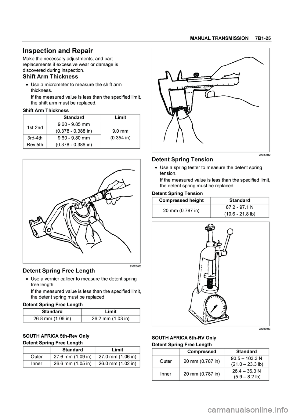
Shift Arm Thickness
� Use a micrometer to measure the shift arm
thickness.
If the measured value is less than the specified limit,
the shift arm must be replaced.
Shift Arm Thickness
Standard Limit
1st-2nd 9.60 - 9.85 mm
(0.378 - 0.388 in)
3rd-4th
Rev.5th 9.60 - 9.80 mm
(0.378 - 0.386 in) 9.0 mm
(0.354 in)
230RS006
Detent Spring Free Length
� Use a vernier caliper to measure the detent spring
free length.
If the measured value is less than the specified limit,
the detent spring must be replaced.
Detent Spring Free Length
Standard Limit
26.8 mm (1.06 in) 26.2 mm (1.03 in)
SOUTH AFRICA 5th-Rev Only
Detent Spring Free Length
Standard Limit
Outer 27.6 mm (1.09 in) 27.0 mm (1.06 in)
Inner 26.6 mm (1.05 in) 26.0 mm (1.02 in)
220RS012
Detent Spring Tension
�
Use a spring tester to measure the detent spring
tension.
If the measured value is less than the specified limit,
the detent spring must be replaced.
Detent Spring Tension
Compressed height Standard
20 mm (0.787 in) 87.2 - 97.1 N
(19.6 - 21.8 lb)
220RS013
SOUTH AFRICA 5th-RV Only
Detent Spring Free Length
Compressed Standard
Outer 20 mm (0.787 in) 93.5 – 103.3 N
(21.0 – 23.3 lb)
Inner 20 mm (0.787 in) 26.4 – 36.3 N
(5.9 – 8.2 lb)
Page 3190 of 4264

7B1-26 MANUAL TRANSMISSION
Reassembly
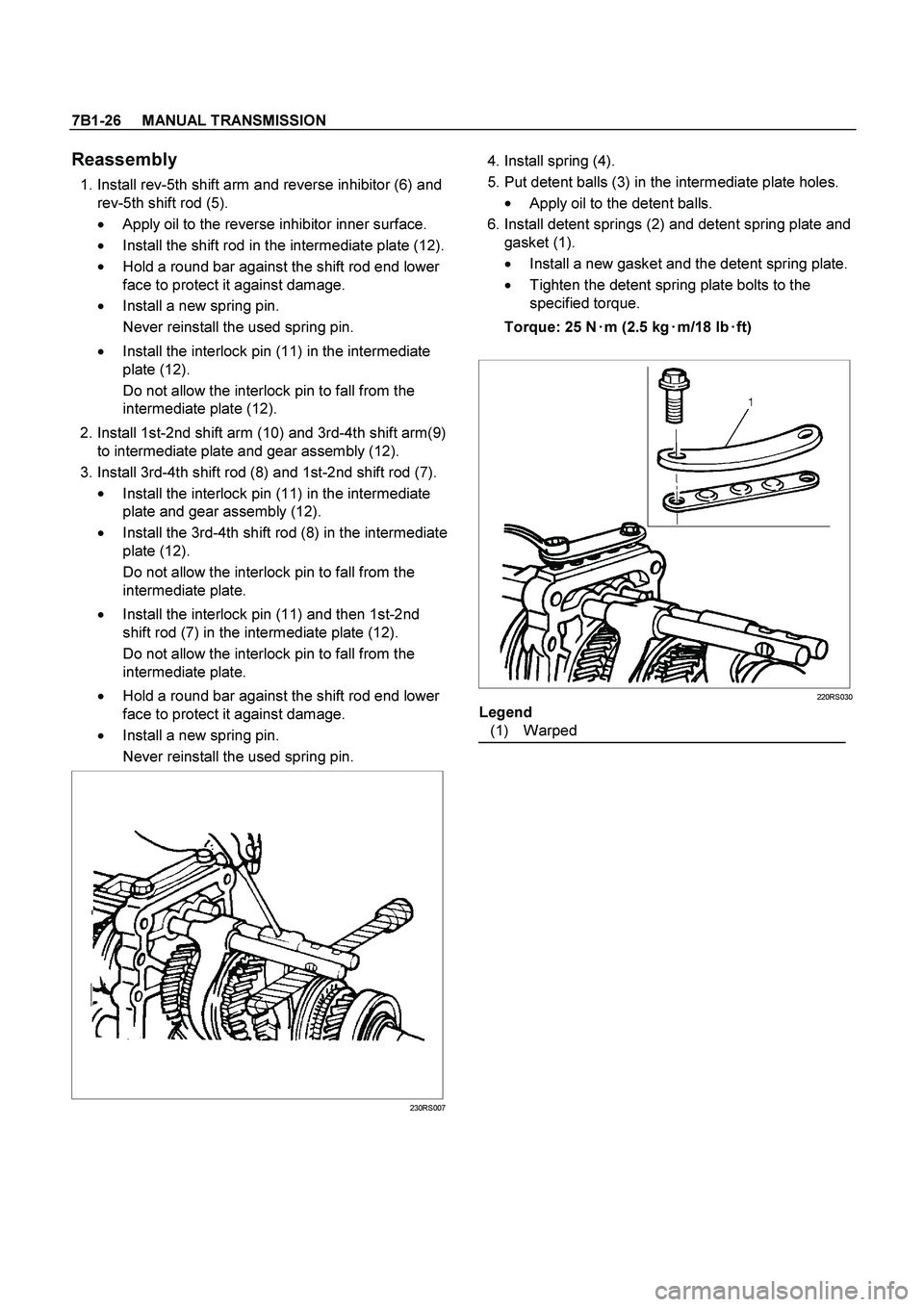
1. Install rev-5th shift arm and reverse inhibitor (6) and
rev-5th shift rod (5).
� Apply oil to the reverse inhibitor inner surface.
� Install the shift rod in the intermediate plate (12).
�
Hold a round bar against the shift rod end lower
face to protect it against damage.
� Install a new spring pin.
Never reinstall the used spring pin.
�
Install the interlock pin (11) in the intermediate
plate (12).
Do not allow the interlock pin to fall from the
intermediate plate (12).
2. Install 1st-2nd shift arm (10) and 3rd-4th shift arm(9)
to intermediate plate and gear assembly (12).
3. Install 3rd-4th shift rod (8) and 1st-2nd shift rod (7).
�
Install the interlock pin (11) in the intermediate
plate and gear assembly (12).
�
Install the 3rd-4th shift rod (8) in the intermediate
plate (12).
Do not allow the interlock pin to fall from the
intermediate plate.
�
Install the interlock pin (11) and then 1st-2nd
shift rod (7) in the intermediate plate (12).
Do not allow the interlock pin to fall from the
intermediate plate.
�
Hold a round bar against the shift rod end lower
face to protect it against damage.
� Install a new spring pin.
Never reinstall the used spring pin.
230RS007
4. Install spring (4).
5. Put detent balls (3) in the intermediate plate holes.
�
Apply oil to the detent balls.
6. Install detent springs (2) and detent spring plate and
gasket (1).
�
Install a new gasket and the detent spring plate.
�
Tighten the detent spring plate bolts to the
specified torque.
Torque: 25 N�
�� �m (2.5 kg�
�� �m/18 lb�
�� �ft)
220RS030
Legend
(1) Warped
Page 3191 of 4264
MANUAL TRANSMISSION 7B1-27
Reverse Gear and 5th Gear
Disassembled View
226R300027
Legend
(1) Bearing Snap Ring (11) Reverse Idler Gear Assembly
(2) Ball Bearing (12) Idle Shaft Pin
(3) Bearing Snap Ring (13) Thrust Washer
(4) Speedometer Drive Gear (14) Reverse Idler Gear
(5) Clip (15) Reverse Idler Shaft
(6) Retainer Snap Ring (16) Bearing Snap Ring
(7) Retainer (17) Ball Bearing
(8) Thrust Plate (18) Counter 5th Gear
(9) Thrust Washer and Lock Ball (19) Counter Reverse Gear
(10) Reverse Idler Gear Snap Ring (20) 5th Gear
Page 3192 of 4264
7B1-28 MANUAL TRANSMISSION
(21) 5th Block Ring (26) Reverse Gear
(22) Needle Bearing (27) Needle Baring
(23) Mainshaft Nut (28) Bearing Plate and Screw
(24) Rev-5th Synchronizer Assembly (29) Bearing Snap Ring
(25) Reverse Block Ring (30) Intermediate Plate
Page 3193 of 4264
MANUAL TRANSMISSION 7B1-29
Disassembly
1. Use a pair of snap ring pliers to remove the bearing
snap ring (1).
2. Set the bearing remover 5-8840-2155-0 and puller
5-8840-2027-0 to the bearing (2) and the mainshaft
end to remove the ball bearing (2).
262L100001
3. Remove the bearing snap ring (3), clip (5),
speedometer drive gear (4), retainer snap ring (6)
and retainer (7).
4. Remove thrust plate (8) and thrust washer and lock
ball (9).
5. Use a pair of snap ring pliers to remove reverse idler
gear snap ring (10).
226RS004
6. Remove the reverse idler gear assembly (11) from
the intermediate plate (30).
226RS005
7. Remove idle shaft pin (12), thrust washer (13),
reverse idler gear (14), and reverse idler shaft (15).
8. Use a pair of snap ring pliers to remove the snap
ring (16).
9. Attach a universal puller to the counter gear shaft.
Use a universal puller to remove the ball bearing
(17) and the counter 5th gear (18).
226RS006
10. Remove counter reverse gear (19).
Page 3194 of 4264
7B1-30 MANUAL TRANSMISSION
11. Remove 5th gear (20), 5th block ring (21), and
needle bearing (2 piece type) (22).
226RS007
12. Remove the mainshaft nut (23) according to
following steps.
Attach the holding fixture 5-8840-2160-0 and base
5-8840-0003-0 to the mainshaft and the counter
gear.
226RW212
� Engage the 3rd-4th synchronizer with the 3rd
gear.
�
Engage the 1st-2nd synchronizer with the 1st
gear.
226RW210
�
Use the mainshaft nut wrench 5-8840-2156-0 to
remove the mainshaft nut (23).
226RW211
Page 3195 of 4264

MANUAL TRANSMISSION 7B1-31
13. Use screw drivers between the reverse gear (26)
and bearing plate (28) to remove the Rev-5th
synchronizer assembly (24) together with reverse
block ring (25) and reverse gear (26).
226RS010
14. Remove needle bearing (27).
15. Use the torx bit wrench (T45) 5-8840-0047-0 to
remove the bearing plate and screw(28) from the
intermediate plate.
220RW137
16. Use the snap ring pliers (1) to remove the mainshaft
bearing snap ring (2) (29).
226RS011
17. Hold the snap ring open with the pliers.
Push the intermediate plate (30) toward the rear of
the transmission to remove it.
The bearing snap ring (29) will come free.
Inspection and Repair
Refer to Top Gear Shaft, Main Gear Shaft, and Counter
Gear in this section for inspection and repair.
Reassembly
1. Mesh the counter gear with the mainshaft assembly.
Set the holding fixture 5-8840-2160-0 to the
mainshaft and the counter gear and then install it on
the base 5-8840-0003-0.
Install the intermediate plate (30) on the gear
assembly.
226RW212