Page 3220 of 4264
7B1-56 MANUAL TRANSMISSION
2. HARD SHIFTING
Checkpoint Trouble Cause Countermeasure
Change lever play
Clutch pedal free play
Repair or replace the
applicable parts and regrease
Readjust the clutch pedal free
play
Worn change lever sliding
portions
Improper clutch pedal free
play
Change lever operationRepair or regrease the change
lever assembly
Replenish or replace the
engine oil
Hard operating change lever
caused insufficient grease
Insufficient or improper gear
oil
OK
OKNG NG NG NG
OK OKGear oil
Continued on the next page
Shift rod and quadrant box
sliding faces, and other partsReplace the shidt rod and/or
the quadrant boxWorn shift rod and/or sliding
faces
Repair or replace the sleeveSleeve movement failure
NG NG
OKShift block sleeve movement
Page 3221 of 4264
MANUAL TRANSMISSION 7B1-57
Checkpoint Trouble Cause Countermeasure
Synchronizer assembly
Shift arm and synchronizer
sleeve
Replace the worn parts
Replace the worn parts
Worn synchronizer parts
Worn shift arm and/or
synchronizer sleeve groove
Mainshaft and countershaft
thrust playReplace the worn partsWorn thrust washer, collar,
and/or gear thrust faces
OK
NG NG NG
OK OK
Continued from the previous
Page 3222 of 4264
7B1-58 MANUAL TRANSMISSION
3. WALKING OR JUMPING OUT OF GEAR
Checkpoint Trouble Cause Countermeasure
Shift rod and quadrant box
sliding faces
Detent ball
Replace the shift rod and/or
the quadrant box
Replace the detent ball
Worn shift rod and/or sliding
faces
Worn detent ball
Detent springRepair or replace the detent
spring
Replace the worn parts
Detent spring weak or broken
Insufficient stroke caused by
sliding position wear and
excessive play
OK
OKNG NG NG NG
OK OK
Change lever play
Continued on the next page
Mainshaft and countershaft
thrust playReplace the worn partsWorn thrust washer, collar,
and/or gear thrust faces
Replace the worn partsWorn shift arm and/or
synchronizer sleeve groove
NG NG
OKShift arm and synchronizer
sleeve
Page 3223 of 4264
MANUAL TRANSMISSION 7B1-59
Checkpoint Trouble Cause Countermeasure
Synchronizer assembly
Bearings (Mainshaft,
countershaft, and individual
gears)
Replace the spring
Replace the bearing(s)
Weak or broken spring
Worn or broken bearings(s)
Mainshaft splines
Synchronizer clutch hub
splinesReplace the main shaft and
the synchronizer clutch hubWorn splines
OK
NG NG NG
OK OK
Continued from the previous page
Page 3224 of 4264
7B1-60 MANUAL TRANSMISSION
4. OIL LEAKAGE
Checkpoint Trouble Cause Countermeasure
Gear oilReplace the gear oilImproper gear oil
Drain plug and/or filler plugTighten the plug(s) and
replenish the oil
Drain the oil to the correct
level
Loose plug(s)
Oil level too high
OKNG NG NG
OK OKOil level
Rear cover oil seal
Air breather
Replace the oil seal
Install the air breather
Replace the air breather
Worn or scratched oil seal
Air breather not installed
Air breather clogged
Front cover oil sealReplace the oil seal
Replace the gasket(s)
Worn or scratched oil seal
Defective or improperly
installed gasket(s)
OK
NG NG NG NG
OK OKGaskets
Page 3225 of 4264
MANUAL TRANSMISSION 7B1-61
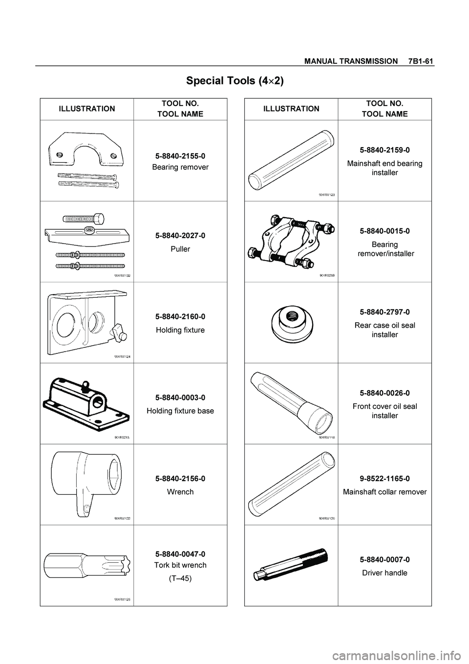
Special Tools (4�
�� �
2)
ILLUSTRATION TOOL NO.
TOOL NAME ILLUSTRATION TOOL NO.
TOOL NAME
5-8840-2155-0
Bearing remover 5-8840-2159-0
Mainshaft end bearing
installer
5-8840-2027-0
Puller 5-8840-0015-0
Bearing
remover/installer
5-8840-2160-0
Holding fixture 5-8840-2797-0
Rear case oil seal
installer
5-8840-0003-0
Holding fixture base 5-8840-0026-0
Front cover oil seal
installer
5-8840-2156-0
Wrench 9-8522-1165-0
Mainshaft collar remover
5-8840-0047-0
Tork bit wrench
(T–45) 5-8840-0007-0
Driver handle
Page 3226 of 4264
. REFER TO THE SRS
COMPONENT AND WIRING LOCATION VIEW IN
ORDER TO DETERMINE WHET")
7B1-62 MANUAL TRANSMISSION
Service Precaution
WARNING: THIS VEHICLE HAS A SUPPLEMENTAL
RESTRAINT SYSTEM (SRS). REFER TO THE SRS
COMPONENT AND WIRING LOCATION VIEW IN
ORDER TO DETERMINE WHETHER YOU ARE
PERFORMING SERVICE ON OR NEAR THE SRS
COMPONENTS OR THE SRS WIRING. WHEN YOU
ARE PERFORMING SERVICE ON OR NEAR THE
SRS COMPONENTS OR THE SRS WIRING, REFER
TO THE SRS SERVICE INFORMATION. FAILURE TO
FOLLOW WARNINGS COULD RESULT IN POSSIBLE
AIR BAG DEPLOYMENT, PERSONAL INJURY, OR
OTHERWISE UNNEEDED SRS SYSTEM REPAIRS. CAUTION: Always use the correct fastener in the
proper location. When you replace a fastener, use
ONLY the exact part number for that application.
ISUZU will call out those fasteners that require a
replacement after removal. ISUZU will also call out
the fasteners that require thread lockers or thread
sealant. UNLESS OTHERWISE SPECIFIED, do not
use supplemental coatings (Paints, greases, or
other corrosion inhibitors) on threaded fasteners or
fastener joint interfaces. Generally, such coatings
adversely affect the fastener torque and the joint
clamping force, and may damage the fastener.
When you install fasteners, use the correct
tightening sequence and specifications. Following
these instructions can help you avoid damage to
parts and systems.
Page 3227 of 4264
MANUAL TRANSMISSION 7B1-63
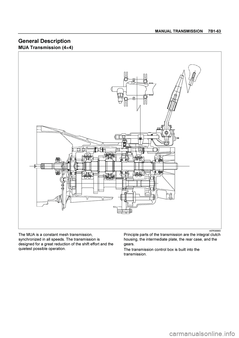
General Description
MUA Transmission (4�
�� �4)
A07R300003
The MUA is a constant mesh transmission,
synchronized in all speeds. The transmission is
designed for a great reduction of the shift effort and the
quietest possible operation.
Principle parts of the transmission are the integral clutch
housing, the intermediate plate, the rear case, and the
gears.
The transmission control box is built into the
transmission.


Replace the spring
Replace the bearing(s)
W")
 and
repl")