Page 4228 of 4264
7A4-54 UNIT REPAIR (JR405E)
TRANSMISSION CASE
02CASE-BK06
Legend
1. Transmission case
2. Spring pin (slender)
3. Spring pin (fat)
4. Manual plate
5. Detent spring
6. Parking rod
7. Manual shaft
8. Oil seal
9. Inhibitor switch
Page 4232 of 4264
7A4-58 UNIT REPAIR (JR405E)
Free length = 22.3 mm (0.878 in)
Linear diameter = 1.1 mm (0.043 in)
12CASE-AY06
Reassembly steps
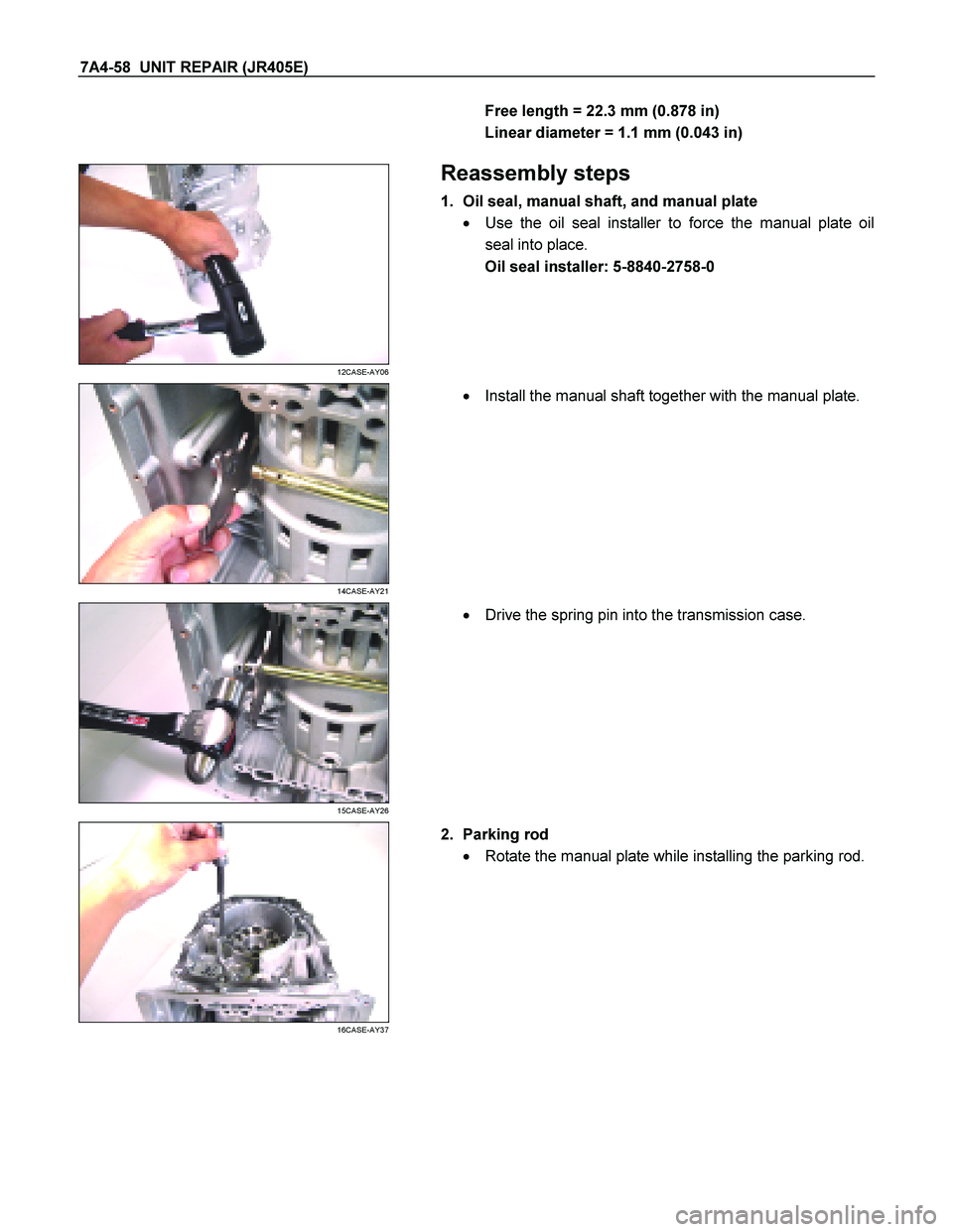
1. Oil seal, manual shaft, and manual plate
� Use the oil seal installer to force the manual plate oil
seal into place.
Oil seal installer: 5-8840-2758-0
14CASE-AY21
�
Install the manual shaft together with the manual plate.
15CASE-AY26
�
Drive the spring pin into the transmission case.
16CASE-AY37
2. Parking rod
� Rotate the manual plate while installing the parking rod.
Page 4233 of 4264
UNIT REPAIR (JR405E) 7A4-59
18CASE-AY43
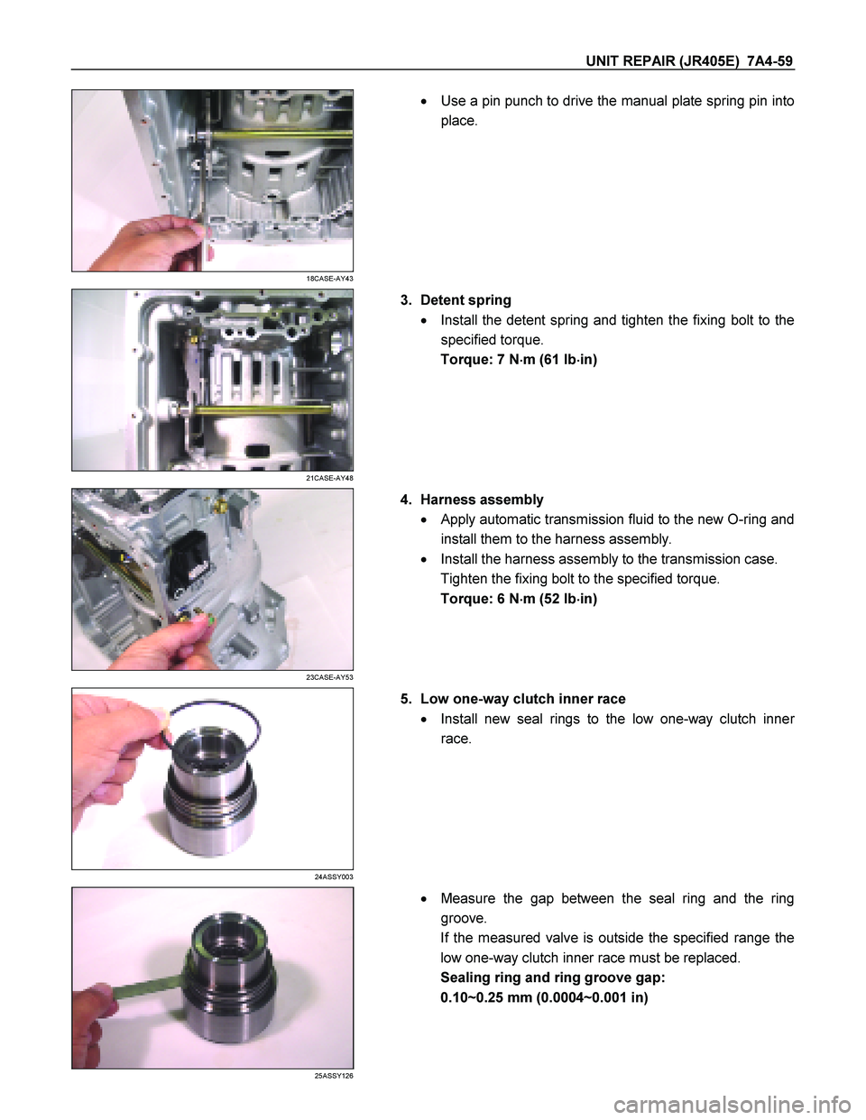
�
Use a pin punch to drive the manual plate spring pin into
place.
21CASE-AY48
3. Detent spring
� Install the detent spring and tighten the fixing bolt to the
specified torque.
Torque: 7 N �
��
�
m (61 Ib �
��
�
in)
23CASE-AY53
4. Harness assembly
� Apply automatic transmission fluid to the new O-ring and
install them to the harness assembly.
� Install the harness assembly to the transmission case.
Tighten the fixing bolt to the specified torque.
Torque: 6 N �
��
�
m (52 Ib �
��
�
in)
24ASSY003
5. Low one-way clutch inner race
� Install new seal rings to the low one-way clutch inne
r
race.
25ASSY126
�
Measure the gap between the seal ring and the ring
groove.
If the measured valve is outside the specified range the
low one-way clutch inner race must be replaced.
Sealing ring and ring groove gap:
0.10~0.25 mm (0.0004~0.001 in)
Page 4255 of 4264
UNIT REPAIR (JR405E) 7A4-81
43ASSY119
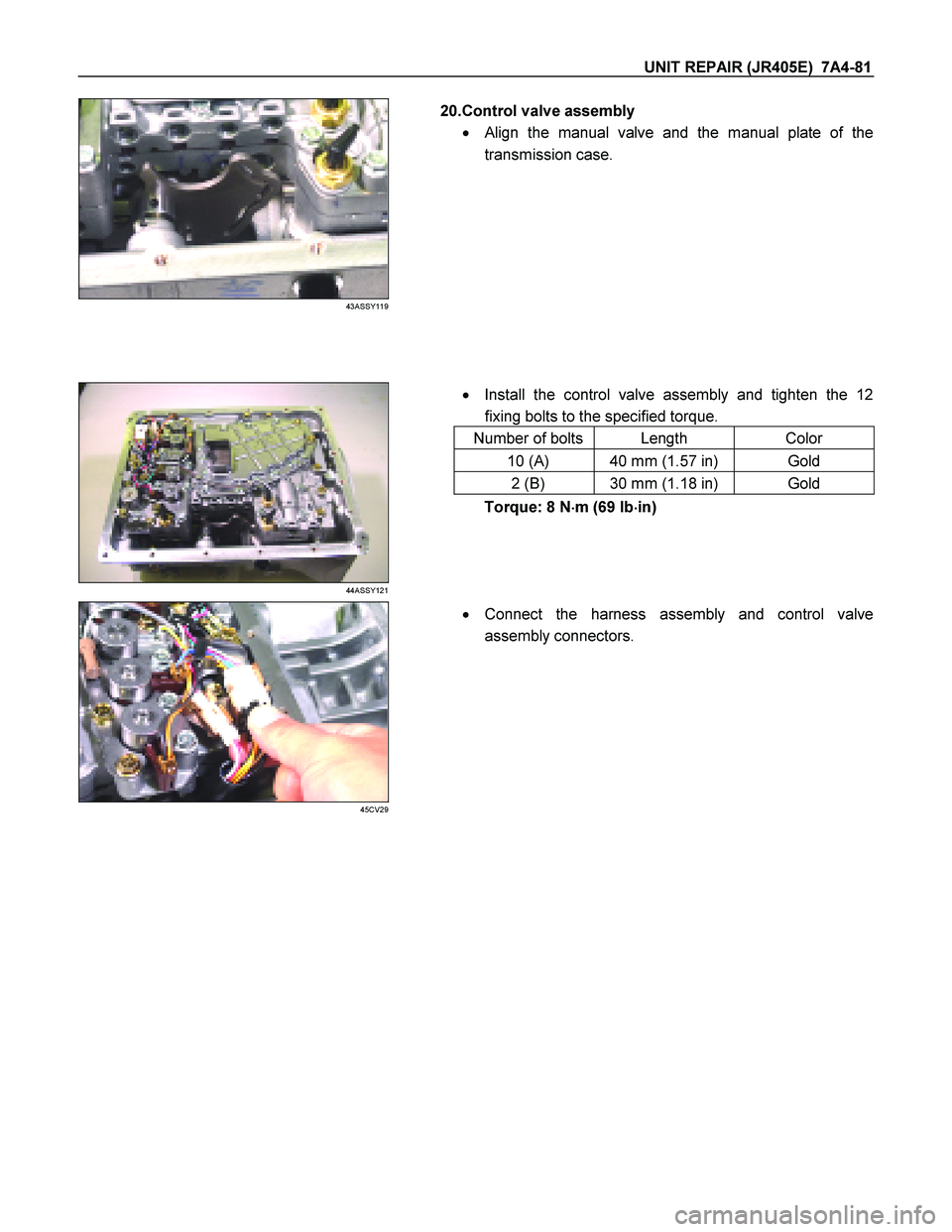
20.Control valve assembly
�
Align the manual valve and the manual plate of the
transmission case.
� Install the control valve assembly and tighten the 12
fixing bolts to the specified torque.
Number of bolts Length Color
10 (A) 40 mm (1.57 in) Gold
2 (B) 30 mm (1.18 in) Gold
44ASSY121
Torque: 8 N �
��
�
m (69 Ib �
��
�
in)
45CV29
�
Connect the harness assembly and control valve
assembly connectors.
Page 4256 of 4264
7A4-82 UNIT REPAIR (JR405E)
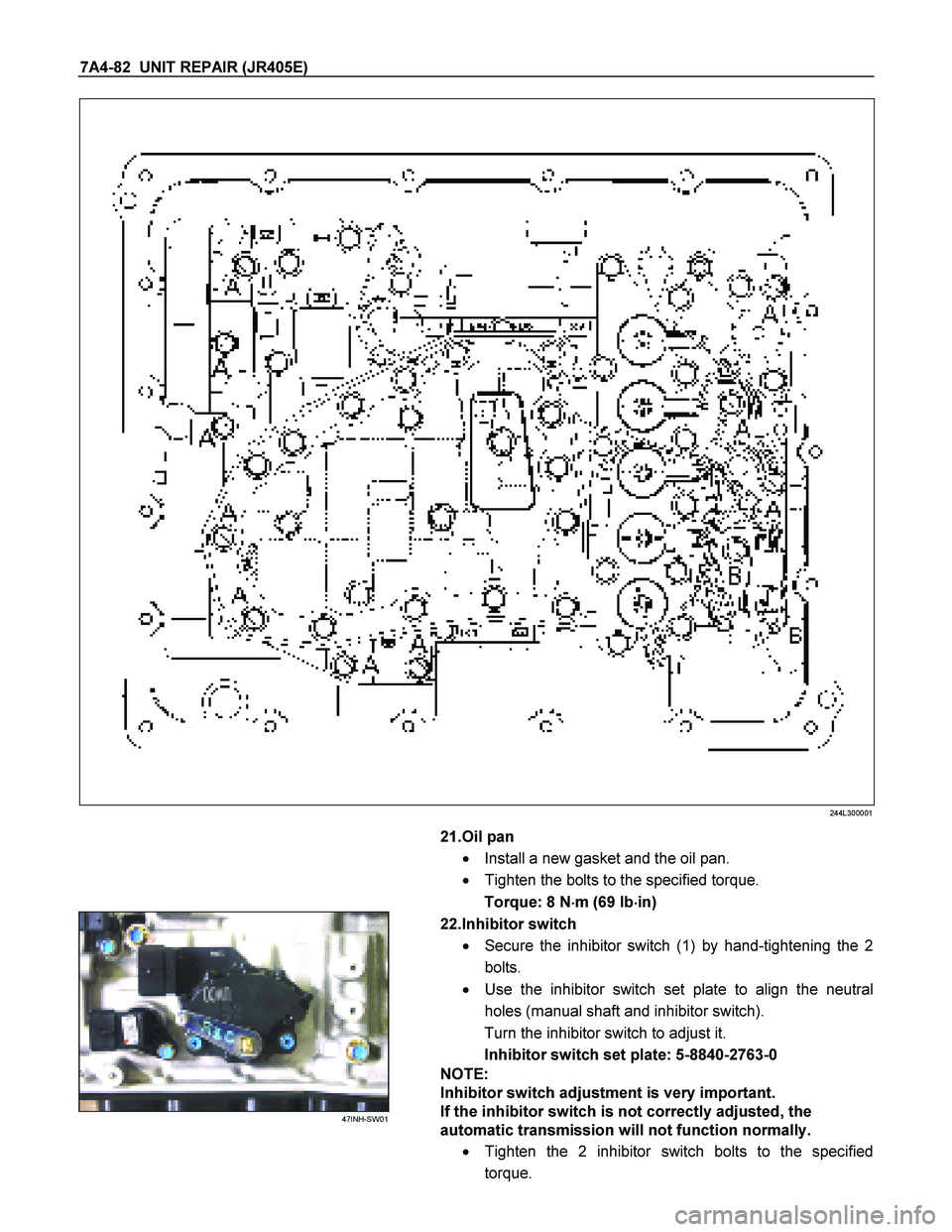
244L300001
21.Oil pan
� Install a new gasket and the oil pan.
� Tighten the bolts to the specified torque.
Torque: 8 N �
��
�
m (69 Ib �
��
�
in)
47INH-SW01
22.Inhibitor switch
� Secure the inhibitor switch (1) by hand-tightening the 2
bolts.
� Use the inhibitor switch set plate to align the neutral
holes (manual shaft and inhibitor switch).
Turn the inhibitor switch to adjust it.
Inhibitor switch set plate: 5-8840-2763-0
NOTE:
Inhibitor switch adjustment is very important.
If the inhibitor switch is not correctly adjusted, the
automatic transmission will not function normally.
� Tighten the 2 inhibitor switch bolts to the specified
torque.

TRANSMISSION CASE
02CASE-BK06
Legend
1. Transmission case
2. Spring pin (slender)
3. Spring pin (fat)
4. Manual plate
5. Detent spring
6. P")