Page 3180 of 4264
. (Diesel engine only)
NOTE: Tighten the lower bolt temporarily.
After installing the fuel pipe assembly, tighten the bolt to
the specified")
7B1-16 MANUAL TRANSMISSION
6. Install starter(15). (Diesel engine only)
NOTE: Tighten the lower bolt temporarily.
After installing the fuel pipe assembly, tighten the bolt to
the specified torque.
Torque: 76 N�
�� �m (7.7 kg�
�� �m/56 lb�
�� �ft)
7. Install the rear support rubber (14) on the
transmission and tighten the nuts to the specified
torque.
Torque: 52 N�
�� �m (5.3 kg�
�� �m/38 lb�
�� �ft)
8. Install the middle part of transmission crossmember
(12) and bolts.
Tighten the nuts to the specified torque.
Torque: 67 N�
�� �m (6.8 kg�
�� �m/49 lb�
�� �ft)
9. Install engine rear mount nuts (11) fixing on
transmission crossmember (12).
Torque: 52 N�
�� �m (5.3 kg�
�� �m/38 lb�
�� �ft)
Remove the transmission jack from transmission
side.
10. Apply grease to top hole portion of the shift fork.
Install slave cylinder (10) and tighten the bolts to the
specified torque.
Torque: 76 N�
�� �m (7.7 kg�
�� �m/56 lb�
�� �ft)
11. Install the fuel pipe brackets (9) on the transmission.
Install the fuel pipe assembly to the fuel brackets.
Torque: Bolt & Nut 76 N�
�� �m (7.7 kg�
�� �m/56 lb�
�� �ft)
Nut 37 N�
�� �
m (3.8 kg�
�� �
m/28 lb�
�� �
ft)
Diesel engine
220R300012
Legend
(1) Bolt
(2) Nut
(3) Fuel Pipe Assembly
6VE1, C24NE
Scan-1
12. Connect transmission harness connectors and clip.
Connector: neutral switch, car speed sensor, and
backup switch.
13. Tighten exhaust pipe fixing nuts (7) to the specified
torque. (Diesel engine only)
Torque: 67 N�
�� �m (6.8 kg�
�� �m/49 lb�
�� �ft)
150R300003
Page 3181 of 4264
. (6VE1)
Torque: 67 N�
�� �m (6.8 kg�
�� �m/49 lb�
�� �ft)
RTW37ASH000101
15. Install rear propeller shaft (6).
Torque: 63 N�
�� �")
MANUAL TRANSMISSION 7B1-17
14. Install the exhaust pipe (8). (6VE1)
Torque: 67 N�
�� �m (6.8 kg�
�� �m/49 lb�
�� �ft)
RTW37ASH000101
15. Install rear propeller shaft (6).
Torque: 63 N�
�� �m (6.4 kg�
�� �m/46 lb�
�� �ft)
16. Install center bearing on crossemember.
Torque: 69 N�
�� �m (7.0 kg�
�� �m/51 lb�
�� �ft)
17. Install gear control lever (5).
Torque: 19 N�
�� �m (1.9 kg�
�� �m/14 lb�
�� �ft)
18. Install grommet assembly (4).
Torque: Screw 1.4 N�
�� �m (0.14 kg�
�� �m/12 lb�
�� �in)
Nut 7 N�
�� �m (0.7 kg�
�� �m/61 lb�
�� �in)
RTW47BMH000101
Legend
(1) Grommet Assembly
(2) Floor Panel
(3) Front
19. Install front floor console (3) and rear floor console
(2).
20. Install gear control lever knob (1).
To the female thread portion, adhesive (TB1344 or
LOCTITE 222 or equiv.) of 3 - 4 drops to be applied
and transmission knob tightened.
Torque: 9 N�
�� �m (0.9 kg�
�� �m/78 lb�
�� �in)
After tightening to specified torque, knob
rewrenched until direction of shift pattern due
positioned.
21. Connect battery ground cable.
Page 3182 of 4264
7B1-18 MANUAL TRANSMISSION
Transmission Case
Major Component
RTW37BLF0005
Legend
(1) Gear Control Box Assembly and Gasket (9) Front Cover (with Oil Seal)
(2) Speedometer Sensor and Driven Gear (10) Top Gear Bearing Snap Ring
(3) Rear Cover Assembly (11) Release Bearing : C24NE
(4) Intermediate Plate with Gear Assembly (12) Shift Fork : C24NE
(5) Transmission Case (13) Fulcrum Bridge : 6VE1
(6) Release Bearing (with Spring) : Diesel engine (14) Release Bearing : 6VE1
(7) Shift Fork : Diesel engine (15) Shift Fork : 6VE1
(8) Counter Front Bearing Snap Ring
Page 3183 of 4264

MANUAL TRANSMISSION 7B1-19
Disassembly
1. Clean the exterior of the unit with solvent.
2. Remove the drain plug from the transmission case
and drain the lubricant.
3. Remove the clutch release bearing with spring
(6)(11) from the transmission case.
4. Remove the shift fork (7)(12), and boot. (Diesel
engine, C24NE)
5. Remove the shift fork snap pin. (6VE1)
6. Remove the shift fork pin and shift fork from the
fulcrum bridge. (6VE1)
RTW47BSH000601
Legend
(1) Shift fork pin
(2) Shift fork
(3) Release bearing
7. Remove the fulcrum bridge from the transmission
case. (6VE1)
RTW37ASH0002
Legend
(1) Fulcrum bridge
8. Remove the front cover (9) and gasket from the
transmission case.
9. Remove snap ring (8) fixing counter front bearing.
10. Use a pair of snap ring pliers to remove the snap
ring (10) fixing top gear bearing.
226RS001
11. Remove the speedometer sensor (2).
Remove the plate (2).
Remove the driven gear bushing and driven gear
(2).
NOTE : Apply a reference mark to the driven gear
bushing before removal.
12. Remove gear control box assembly (1).
Page 3184 of 4264
 from the
transmission case (5) and intermediate plate (4).
14. Remove intermediate plate with gear assembly (4)
from transm")
7B1-20 MANUAL TRANSMISSION
13. Remove the rear cover assembly (3) from the
transmission case (5) and intermediate plate (4).
14. Remove intermediate plate with gear assembly (4)
from transmission case (5).
Reassembly
1. Apply recommended liquid gasket (LOCTITE 17430)
or its equivalent to the transmission case (5),
intermediate plate (4) and rear cover (3) fitting
surfaces.
2. Install the intermediate plate with gear assembly (4)
to the transmission case (5).
Pull out the top gear shaft until the ball bearing snap
ring groove protrudes from the transmission case
front cover fitting face.
Avoid subjecting the main shaft to sudden shock or
stress.
3. Install the rear cover with oil seal (3) on the
intermediate plate with gear (4) by performing the
following steps.
�
Cover the shaft splines with adhesive tape.
This will prevent damage to the oil seal lip. 4. Install a new gasket and gear control box assembly
(1).
Install the harness clips and brackets and then
tighten four new gear control box bolts to the
specified torque.
Torque: 20 N�
�� �m (2.0 kg�
�� �m/14 lb�
�� �ft)
261R300004
5. Install the O-ring (4) to the speedometer driven gear
bushing (3).
Install the driven gear to the speedometer driven
gear bushing (3).
6. Install the speedometer driven gear assembly (2) to
the transmission rear cover (3).
Install the plate (1) to the transmission rear cover
(3).
Torque: 15 N�
�� �m (1.5 kg�
�� �m/11 lb�
�� �ft)
Page 3185 of 4264
.
Torque: 27 N�
�� �m (2.8 kg�
�� �m/20 lb�
�� �ft)
225R300001
8. Install top gear bearing snap ring (10) and counter
front")
MANUAL TRANSMISSION 7B1-21
7. Install the speedometer sensor (2).
Torque: 27 N�
�� �m (2.8 kg�
�� �m/20 lb�
�� �ft)
225R300001
8. Install top gear bearing snap ring (10) and counter
front bearing snap ring (8).
�
Use a pair of snap ring pliers to install the snap
rings to the mainshaft and countershaft.
�
The snap rings must be fully inserted into the
bearing snap ring groove.
9. Front cover with oil seal (9).
Front Cover Oil Seal Replacement
�
Remove the oil seal from the front cover.
�
Apply engine oil to a new oil seal outer
circumference.
�
Apply recommended grease to the oil seal lip.
�
Use the oil seal installer 5-8840-0026-0 to install
the oil seal to the front cover.
220R3000020
10. Install a new gasket and front cover (9) to the
transmission case.
NOTE: Take care not to damage the oil seal.
Notes When Tightening the Bolt:
�
After cleaning the bolt hole, dry it thoroughly with air.
�
After cleaning the screw face of a removed bolt or
new one, dry it thoroughly. Apply recommended
liquid gasket (LOCTITE 242) or its equivalent before
tightening it.
Tighten six front cover bolts to the specified torque.
Torque: 25 N�
�� �
m (2.6 kg�
�� �
m/19 lb�
�� �
ft)
11. Apply molybdenum disulfide type grease to the
areas as shown in the figure and install shift fork (7).
(Diesel engine, C24NE)
F07L100026
Page 3186 of 4264
7B1-22 MANUAL TRANSMISSION
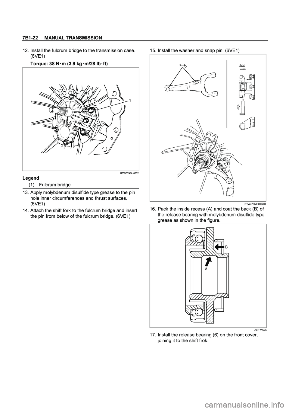
12. Install the fulcrum bridge to the transmission case.
(6VE1)
Torque: 38 N�
�� �
m (3.9 kg�
�� �
m/28 lb�
�� �
ft)
RTW37ASH0002
Legend
(1) Fulcrum bridge
13. Apply molybdenum disulfide type grease to the pin
hole inner circumferences and thrust surfaces.
(6VE1)
14. Attach the shift fork to the fulcrum bridge and insert
the pin from below of the fulcrum bridge. (6VE1)
15. Install the washer and snap pin. (6VE1)
RTW47BMH000201
16. Pack the inside recess (A) and coat the back (B) of
the release bearing with molybdenum disulfide type
grease as shown in the figure.
A07RW075
17. Install the release bearing (6) on the front cover,
joining it to the shift frok.
Page 3187 of 4264
MANUAL TRANSMISSION 7B1-23
Intermediate Plate with Gear Assembly, Detent, Shift Arm, Shift Rod, and
Interlock Pin
Disassembled View
RTW47BLF000501
Legend
(1) Detent Spring Plate and Gasket (7) 1st-2nd Shift Rod
(2) Detent Spring (8) 3rd-4th Shift Rod
(3) Detent Ball (9) 3rd-4th Shift Arm
(4) Spring (10) 1st-2nd Shift Arm
(5) Rev-5th Shift Rod (11) Interlock Pin
(6) Rev-5th Shift Arm and Reverse Inhibitor (12) Intermediate Plate and Gear Assembly
 Gear Control Box Assembly and Gasket (9) Front Cover (with Oil Seal)
(2) Speedometer Sensor and Dri")
 Detent Spring Plate a")