Page 3612 of 4264
7D-24 TRANSFER CASE
Reassembly
Transfer Reassembly
The rear cover oil seals and the rear output shaft ball
bearings cannot be reused. They must be replaced with
new ones when the transfer is reassembled.
1.
Use the oil seal installer (5-8840-2785-0) to press
the new input shaft and/or front output shaft oil seals
into place (If replacement is required).
2.
Use a press to install the ball bearings to the front
output shaft. Be sure that the bearings are fully
inserted and then install the snap ring.
3.
Install the damper ring and the internal gear to the
transfer case. Be sure that the damper ring is
between the internal gear and the case.
226R300004
Note the direction of the dumper ring installation as
figure.
226R300025
Legend
(1) Dumper Ring
(2) Internal Gear
(3) Retaining Ring
Page 3615 of 4264
TRANSFER CASE 7D-27
14.
Insert the H-L sleeve into the main shaft.
226R300023
Legend
(1) H-L Sleeve
(3) Synchronizer Key and Key Spring
(2) 2-4 Sleeve
15.
Install the sleeve to the H-L shift assembly.
16.
Install the sleeve to the 2-4 shift assembly.
17.
Coat the area around each of the shift assembl
y
insertion holes (transfer case) with transfer oil.
18.
Install the main shaft together with the H-L shif
t
assembly and the 2-4 shift assembly to the shif
t
drum.
Page 3616 of 4264
7D-28 TRANSFER CASE
19. Align the shift shaft splines with the shift drum and
install the shafts to the drum.
RTW320MF000201
Legend
(1) H-L Sleeve and Shift ASM
(3) Shift Shaft
(2) 2-4 Sleeve ASM with Main Shaft and Shift ASM
(4) Shift Drum
NOTE: Be careful in the direction of an assembly.
P1010041/020124
20.
Coat the main shaft with oil.
21.
Align the block ring, the outside ring, and the inside
ring with the 2-4 hub assembly and install them.
22.
Assemble the sprocket, transfer chain, and front
output shaft.
23.
Install the sprocket, transfer chain, and front output
shaft to the main shaft and the transfer case.
Page 3617 of 4264

TRANSFER CASE 7D-29
24.
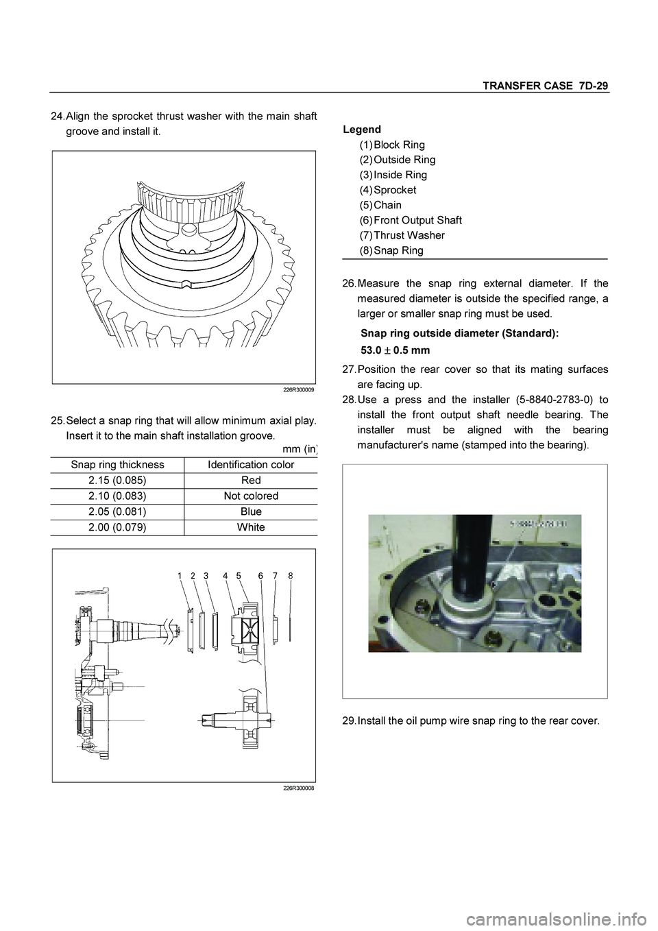
Align the sprocket thrust washer with the main shaft
groove and install it.
226R300009
25. Select a snap ring that will allow minimum axial play.
Insert it to the main shaft installation groove.
mm (in
)
Snap ring thickness
Identification color
2.15 (0.085)
Red
2.10 (0.083)
Not colored
2.05 (0.081)
Blue
2.00 (0.079)
White
226R300008
Legend
(1) Block Ring
(2) Outside Ring
(3) Inside Ring
(4) Sprocket
(5) Chain
(6) Front Output Shaft
(7) Thrust Washer
(8) Snap Ring
26.
Measure the snap ring external diameter. If the
measured diameter is outside the specified range, a
larger or smaller snap ring must be used.
Snap ring outside diameter (Standard):
53.0 �
�� � 0.5 mm
27.
Position the rear cover so that its mating surfaces
are facing up.
28.
Use a press and the installer (5-8840-2783-0) to
install the front output shaft needle bearing. The
installer must be aligned with the bearing
manufacturer's name (stamped into the bearing).
29.
Install the oil pump wire snap ring to the rear cover.
Page 3618 of 4264
7D-30 TRANSFER CASE
226R300005
30.
Temporarily install the speedometer drive gear to the
inside of the rear cover. Pay close attention to
installation direction.
31.
Use a press and the installer (9-8522-1268-0) to
install the rear output shaft ball bearings. Do not
drive the ball bearings into place with a hammer.
32.
Install the rear output shaft retaining ring.
33.
Place the oil pump in its specified position.
34.
Secure the pump strainer to the rear cover and
tighten the bolts to the specified torque.
Rear cover and transfer case bolt torque:
15 Nm (1.5 kgm/11 lb ft)
226R300010
35.
Apply Loctite FMD 127 to the mating surfaces of the
rear cover and the transfer case. Be sure that the
Loctite is evenly applied to the inside surfaces of the
bolt holes with no gaps.
Legend
(1) Oil Pump ASM
(2) Wire Snapring
(3) Retaining Ring
(4) Ball Bearing
(5) Speedometer Gear Drive Gear
(6) Rear Cover
Legend
(1) Wire Snapring
Page 3619 of 4264
TRANSFER CASE 7D-31
226R300011
36.
Install the rear cover to the transfer case and tighten
the bolts to the specified torque.
Rear cover and transfer case bolt torque:
22 Nm (2.2 kgm/16 lbft)
37.
Apply engine oil to the companion flange O-ring.
38.
Install the O-ring to the front output shaft.
39.
Secure the front companion flange with the
companion flange holder (5-8840-0133-0).
40.
Install the end nuts and tighten them to the specified
torque.
Front companion flange end nut torque:
137 Nm (14 kgm/101 lbft)
41.
Use a cold chisel to caulk the front companion
flange end nuts.
226R300012
RUW34DSH000301
Legend
(1) MAX 26mm (1.02 in)
(2) MIN 4mm (0.16 in)
42.
Apply Loctite 575 to the threaded portion of the
detenteplugs.
Page 3620 of 4264

7D-32 TRANSFER CASE
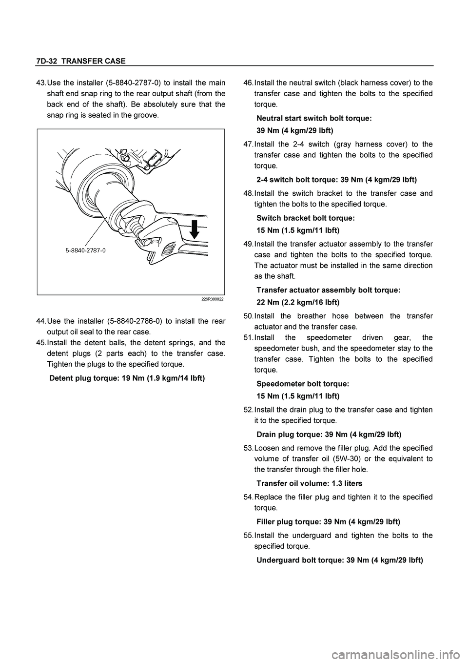
43.
Use the installer (5-8840-2787-0) to install the main
shaft end snap ring to the rear output shaft (from the
back end of the shaft). Be absolutely sure that the
snap ring is seated in the groove.
226R300022
44.
Use the installer (5-8840-2786-0) to install the rea
r
output oil seal to the rear case.
45.
Install the detent balls, the detent springs, and the
detent plugs (2 parts each) to the transfer case.
Tighten the plugs to the specified torque.
Detent plug torque: 19 Nm (1.9 kgm/14 lbft)
46.
Install the neutral switch (black harness cover) to the
transfer case and tighten the bolts to the specified
torque.
Neutral start switch bolt torque:
39 Nm (4 kgm/29 lbft)
47.
Install the 2-4 switch (gray harness cover) to the
transfer case and tighten the bolts to the specified
torque.
2-4 switch bolt torque: 39 Nm (4 kgm/29 lbft)
48.
Install the switch bracket to the transfer case and
tighten the bolts to the specified torque.
Switch bracket bolt torque:
15 Nm (1.5 kgm/11 lbft)
49.
Install the transfer actuator assembly to the transfe
r
case and tighten the bolts to the specified torque.
The actuator must be installed in the same direction
as the shaft.
Transfer actuator assembly bolt torque:
22 Nm (2.2 kgm/16 lbft)
50.
Install the breather hose between the transfe
r
actuator and the transfer case.
51.
Install the speedometer driven gear, the
speedometer bush, and the speedometer stay to the
transfer case. Tighten the bolts to the specified
torque.
Speedometer bolt torque:
15 Nm (1.5 kgm/11 lbft)
52.
Install the drain plug to the transfer case and tighten
it to the specified torque.
Drain plug torque: 39 Nm (4 kgm/29 lbft)
53.
Loosen and remove the filler plug. Add the specified
volume of transfer oil (5W-30) or the equivalent to
the transfer through the filler hole.
Transfer oil volume: 1.3 liters
54.
Replace the filler plug and tighten it to the specified
torque.
Filler plug torque: 39 Nm (4 kgm/29 lbft)
55.
Install the underguard and tighten the bolts to the
specified torque.
Underguard bolt torque: 39 Nm (4 kgm/29 lbft)
Page 3621 of 4264
TRANSFER CASE 7D-33
Main Data and Specifications
General Specifications
Type Synchronized type gears shifting between the 2 and 4 wheel drive mode.
Planetary type gears shifting between “low" and “high".
Control method Remote control with the button switch on the instrument panel for gears
shifting among “2H" , “4H" and “4L".
Gear ratio High; 1.000
Low; 2.482
Oil capacity 1.3 lit. (1.37 U.S. quart)
Type of lubricant BESCO GEAR OIL TRANSAXLE (5W-30)
Refer to chart in Section 0
Torque Specifications
N�m (kg�m/lb ft)
RTW47DLF000201