Page 3539 of 4264
FRONT SUSPENSION 3C-47
14. Install cam plate and nut then tighten lower link nut
finger-tight.
NOTE: Apply oil to the thread.
NOTE: Tighten the nut (3) or bolt with the parts in the
position shown in the illustration below.
Buffer clearance: 29.7 mm (1.17 in)
Torque: 186 N�
�� �m (19.0kg�
�� �m/137 lb ft)
NOTE: Adjust the trim height. Refer to Front En
d
Alignment Inspection and Adjustment in Steering
section.
450R100002
Page 3545 of 4264
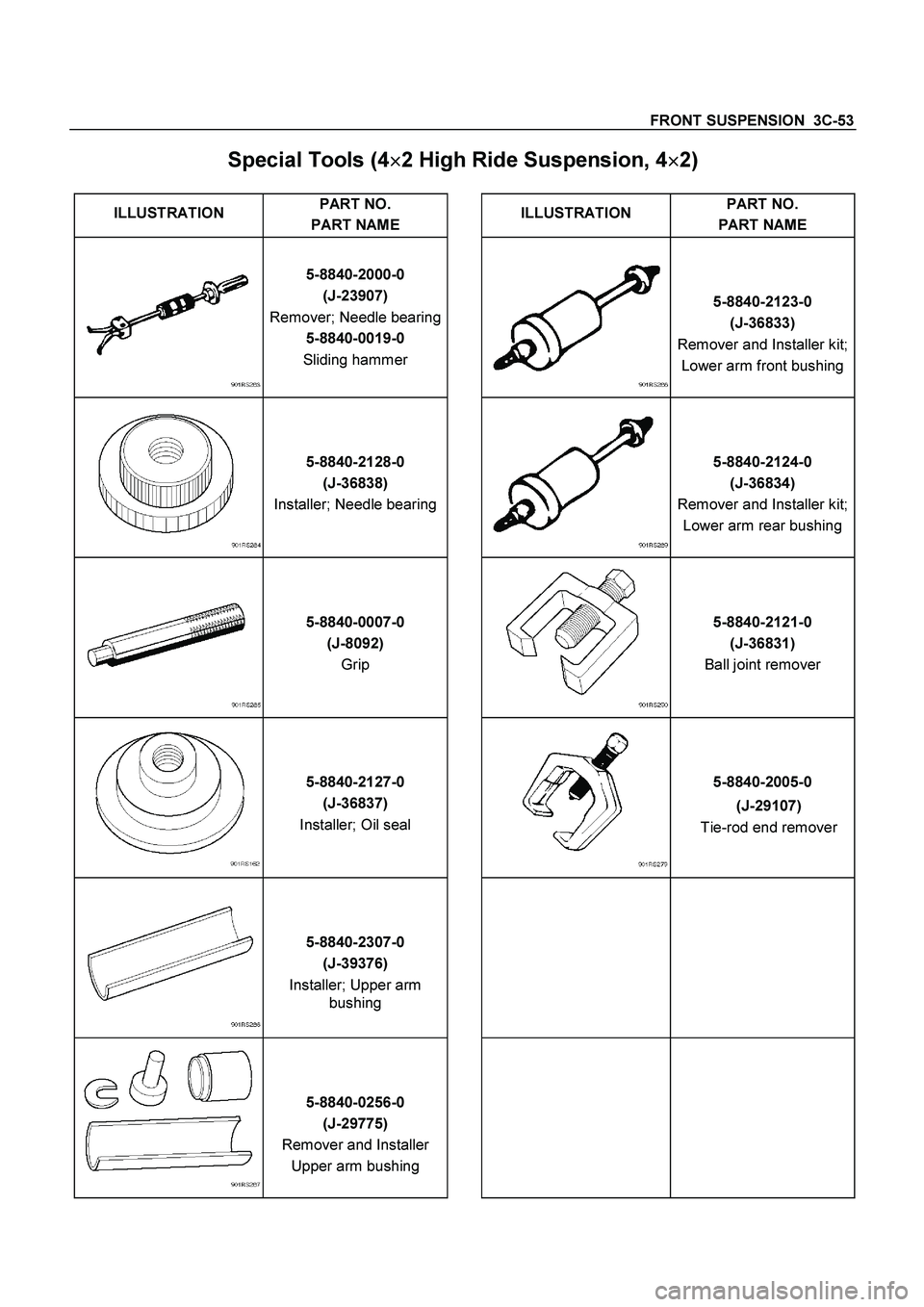
FRONT SUSPENSION 3C-53
Special Tools (4�
�� �
2 High Ride Suspension, 4�
�� �
2)
ILLUSTRATION PART NO.
PART NAME
ILLUSTRATION
PART NO.
PART NAME
5-8840-2000-0
(J-23907)
Remover; Needle bearing
5-8840-0019-0
Sliding hammer 5-8840-2123-0
(J-36833)
Remover and Installer kit;
Lower arm front bushing
5-8840-2128-0
(J-36838)
Installer; Needle bearing 5-8840-2124-0
(J-36834)
Remover and Installer kit;
Lower arm rear bushing
5-8840-0007-0
(J-8092)
Grip 5-8840-2121-0
(J-36831)
Ball joint remover
5-8840-2127-0
(J-36837)
Installer; Oil seal 5-8840-2005-0
(J-29107)
Tie-rod end remover
5-8840-2307-0
(J-39376)
Installer; Upper arm
bushing
5-8840-0256-0
(J-29775)
Remover and Installer
Upper arm bushing
Page 3547 of 4264
FRONT SUSPENSION 3C-55
2. VEHICLE PULLS TO RIGHT OR LEFT
Checkpoint Trouble Cause Countermeasure
Steering linkage, and upper
and lower link
Rubber bushing for upper and
lower link
Wheel alignment
Vehicle trim height
Replace
Replace
Adjust
Adjust
Deformed
Worn
Incorrect
Incorrect
Brake adjustment (binding)
Adjust
Replace
Incorrect
Collapsed or break (4�
2
Except high ride suspension)
Collapsed or twisted (4�
4, 4�
2
High ride suspension)
Continued on the next pageOK OK OK OK
NG NG NG NG NG NG
OK OK Coil spring (4�2 Except high
ride suspension)
Torsion bar (4�
4, 4�
2 High
ride suspension)
Front wheel bearing
Adjust or replace
Incorrect adjustment or
abrasion
NG
Page 3551 of 4264
FRONT SUSPENSION 3C-59
5. NOISES
Checkpoint Trouble Cause Countermeasure
Lubricating oil and grease for
upper and lower ball joint
Shock absorber
Stabilizer fixing nuts and bolts
Upper and lower links
bushings
Replace
Replace
Retighten
Replace
Insufficient
Faulty
Loose
Worn
Shock absorber fixing nut and
bolt
Retighten
Loose
Continued on the next pageOK OK OK OK
NG NG NG NG NG
OK
Upper and lower ball joint
Replace
Damaged
NG
Page 3552 of 4264
3C-60 FRONT SUSPENSION
Checkpoint Trouble Cause Countermeasure
Steering linkage and steering
gearReplaceWorn
AdjustImproper OK
NG NG
OKTire pressure Continued from the previous page
Steering unit fixing bolts and
linkageRetightenLoose
Adjust or replaceIncorrect adjustment or
abrasion OK
NG NG
OKFront wheel bearing
Lubricating oil and grease to
steering linkageReplaceInsufficient NG OK
Page 3564 of 4264
 and bolt and tighten it to the
specified torque.
Torque N�m (kg�m/lb�ft)
42 (4.3/31)
2. Install the leaf spring (14).
�")
3D-8 REAR SUSPENSION
Installation
1. Install the bump rubber (15) and bolt and tighten it to the
specified torque.
Torque N�m (kg�m/lb�ft)
42 (4.3/31)
2. Install the leaf spring (14).
� The leaf spring assembly should be installed so that the
built-in rubber bush is toward the front.
� Align the holes of the spring eye and frame bracket.
� Insert the spring pin (13) toward vehicle inner side
through the frame bracket holes and the spring bush
hole.
� Tighten the nut (12) a little and after the vehicle is
lowered, tighten it to the specified torque.
Torque N
�m (kg
�m/lb
�ft)
152 (15.5/112)
RTW340LF000101
� Apply rubber grease to inside and outside of the rubber
bushing.
� Install the rubber bushings (11) into the hole of the
frame side bracket and the spring rear eye.
� Install the shackle pin (10) and shackle plate (9).
� Tighten the nuts (8) a little and after vehicle is lowered,
tighten it to the specified torque.
Torque N�m (kg�m/lb�ft)
98 (10/72)
3. Support the lower clamp (7) under the leaf spring.
4. Apply oil to the thread portion of U bolt (6).
Install the U bolt and seat on the rear axle and insert the U
bolt in the lower clamp holes.
5. Tighten the nut (5) to the specified torque.
Torque N�m (kg�m/lb�ft)
78 (8.0/58)
6. Install the shock absorber (4) and inner washer on the
lower clamp pin and frame side pin.
7. Install the washer and nut (3) on the frame side pin and
tighten the nut to the specified torque.
Torque N�m (kg�m/lb�ft)
39 (4.0/29)
8. Install the washer and nut (2) on the lower clamp pin and
tighten the nut to the specified torque.
Torque N�m (kg�m/lb�ft)
39 (4.0/29)
9. Install the parking brake cable (1) on the leaf spring and
tighten the nut at its bracket.
Torque N
�m (kg
�m/lb
�ft)
7 (0.7/5)
Page 3570 of 4264
3D-14 REAR SUSPENSION
3. SPRING BREAKAGE
Checkpoint Trouble Cause Countermeasure
Replace
Oil leakage
NG
Shock absorber
Replace
Bushing worn
U-bolts
Shackle pins and pivot pins
Replace
Retighten
Retighten
Damaged
Bolts and nuts for loosening
Bolts and nuts for loosening
Replace
Worn or damaged
OK
OK
NG
NG
NG
NG
NG
OK
Condition of loading
Continued on the next page
Page 3589 of 4264

TRANSFER CASE 7D-1
SECTION 7D
TRANSFER CASE
TABLE OF CONTENTS
PAGE
Service Precaution .......................................................................................................... 7D – 2
General Description ........................................................................................................ 7D – 3
Transfer Rear Oil Seal .................................................................................................... 7D – 4
Transfer Rear Oil Seal and Associated Parts ............................................................ 7D – 4
Removal ........................................................................................................................ 7D – 4
Installation .................................................................................................................... 7D – 4
Transfer Case Assembly ................................................................................................ 7D – 6
Transfer Case Assembly and Associated Parts ........................................................ 7D – 6
Removal ........................................................................................................................ 7D – 7
Installation .................................................................................................................... 7D – 7
Transfer Control Unit ...................................................................................................... 7D – 10
Removal ........................................................................................................................ 7D – 10
Installation .................................................................................................................... 7D – 10
Transfer Disassembly ..................................................................................................... 7D – 11
Removal ........................................................................................................................ 7D – 11
Inspection and Repair .................................................................................................. 7D – 20
Inspection and Repair (Transfer Case Assembly) ..................................................... 7D – 20
Reassembly .................................................................................................................. 7D – 24
Main Data and Specifications ........................................................................................ 7D – 33
Special Tools ................................................................................................................ 7D – 36
 or bolt with the parts in the
position sho")