Page 3592 of 4264
7D-4 TRANSFER CASE
Transfer Rear Oil Seal
Transfer Rear Oil Seal and Associated Parts
220R300018
Legend
(1) Rear Propeller Shaft
(2) Oil Seal
Removal
1.
Disconnect the rear propeller shaft (1) from the
transfer case side.
2.
Remove the oil seal from the transfer case.
Installation
1.
Install oil seal and apply engine oil to the oil seal
outer surfaces.
2.
Apply the recommended grease (BESCO L2) or
equivalent to the oil seal lip.
3.
Use the oil seal installer 5-8840-2786-0 to install the
rear seal (2) to the transfer rear case.
Page 3599 of 4264
TRANSFER CASE 7D-11
Transfer Disassembly
RTW47DLF000101
Legend
(7) Neutral Switch ASM
(1) Transfer Case
(8) Speedometer Bush, Plate and Driven Gear
(2) Companion Flange, O-ring and Nut
(9)Transfer Actuator
(3) Stoneguard
(10)Breather Hose
(4) Detent Plug, Spring and Detent Ball
(11) Heat Protector (Except Diesel Engine)
(5) 2-4 Switch ASM
(6) Switch Bracket
Removal
1.
Remove the stoneguard.
2.
Remove the drain plug from the transfer case to
drain the oil.
3.
Remove the parts listed below.
�
Speedometer bush, plate, and speedomete
r
driven gear
�
Breather hose (Between the transfer case and
the transfer actuator assembly)
�
Transfer actuator assembly
�
Switch bracket
Page 3601 of 4264
TRANSFER CASE 7D-13
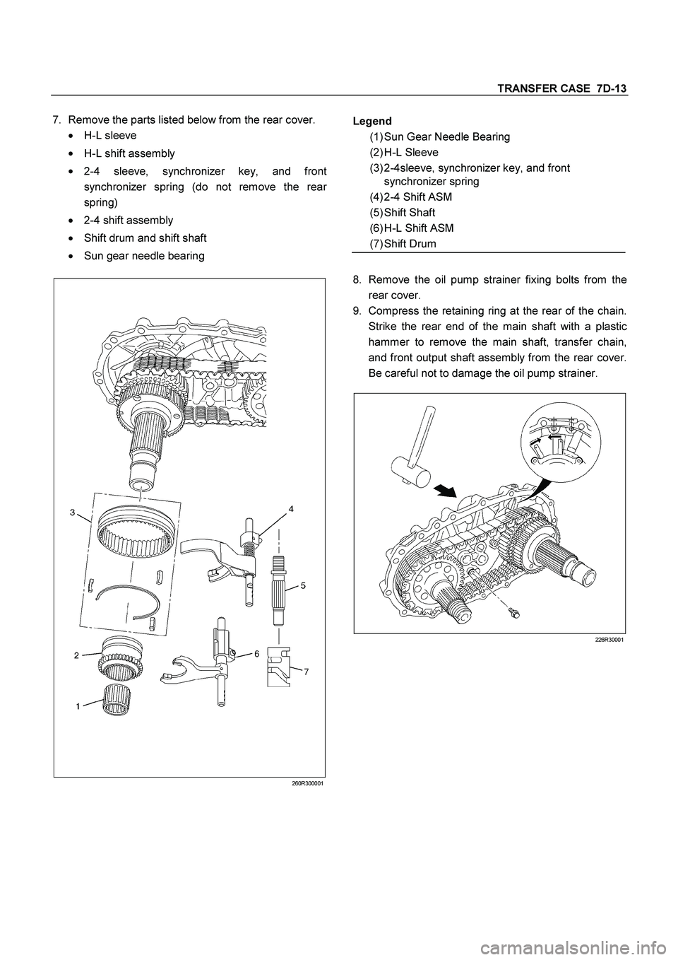
7.
Remove the parts listed below from the rear cover.
�
H-L sleeve
�
H-L shift assembly
�
2-4 sleeve, synchronizer key, and front
synchronizer spring (do not remove the rea
r
spring)
�
2-4 shift assembly
�
Shift drum and shift shaft
�
Sun gear needle bearing
260R300001
8.
Remove the oil pump strainer fixing bolts from the
rear cover.
9.
Compress the retaining ring at the rear of the chain.
Strike the rear end of the main shaft with a plastic
hammer to remove the main shaft, transfer chain,
and front output shaft assembly from the rear cover.
Be careful not to damage the oil pump strainer.
226R30001
Legend
(1) Sun Gear Needle Bearing
(2) H-L Sleeve
(3) 2-4sleeve, synchronizer key, and front
synchronizer spring
(4) 2-4 Shift ASM
(5) Shift Shaft
(6) H-L Shift ASM
(7) Shift Drum
Page 3602 of 4264
7D-14 TRANSFER CASE
10.
Remove the transfer chain and the front output shaft
from the main shaft.
11.
Remove the main shaft snap ring.
12.
Remove the speedometer drive gear, the ball
bearings, the retaining ring, and the oil pump
assembly.
13.
Remove the sprocket snap ring.
14.
Remove the thrust washer, the drive sprocket, the
inside ring, the outside ring, the block ring, and the
rear synchronizer spring.
RTW37DMF000101
Legend
(1) Rear synchronizer spring
(9) Sprocket Snap Ring
(2) Block Ring
(10) Oil Pump ASM
(3) Outside Ring
(11) Oil Pump Retaining Ring
(4) Inside Ring
(12) Retaining Ring
(5) Drive Sprocket
(13) Ball Bearing
(6) Transfer Chain
(14) Speedometer Drive Gear
(7) Front Output shaft
(15) Main Shaft Snap Ring
(8) Thrust Washer
Page 3604 of 4264
7D-16 TRANSFER CASE
23.
Remove the retaining ring (spiral type) together with
the internal gear and the damper ring.
226R300004
24.
Remove the snap ring.
25.
Use a press to remove the front output shaft ball
bearings.
26.
Remove the oil pump wire snap ring from the rea
r
cover.
27.
Use a sliding hammer (5-8840-0084-0) and a needle
bearing replacer (5-8840-2788-0) to remove the
needle bearing from the front output shaft.
P1010023
Legend
(1) Dumper Ring
(2) Internal Gear
(3) Retaining Ring
Page 3607 of 4264
TRANSFER CASE 7D-19
2-4 shift reassembly
1.
Install the shift block assembly to the shift rod.
2.
Install the spring pin. The head of the pin must not
project beyond the surface (1) of the shift block.
226R300015
3.
Install the spring.
4.
Install the shift arm.
5.
Compress the spring and install the snap ring.
6.
Install the guide roller.
Oil pump disassembly
1.
Remove the clamps securing the screen.
2.
Remove the screen.
3.
Remove the clamps securing the hose.
4.
Remove the hose.
NOTE: To maintain and porotect oil pump function, the
pump is constructed so that it cannot be disassembled.
Under no conditions attempt to disassemble the pump.
Oil pump reassembly
1.
Tighten the clamps to secure the hose.
2.
Tighten the clamps to secure the screen.
NOTE: Be carefull in the direction of clamps.
RTW37DSH000101
Legend
(1) OIL PUMP ASM
(2) CLAMP
(3) HOSE
(4) SCREEN ASM
Page 3608 of 4264

7D-20 TRANSFER CASE
Inspection and Repair
1.
Make the necessary repair or parts replacement if
wear, damage or any other abnormal conditions are
found during inspection.
2.
Wash all parts thoroughly in clean solvent. Be sure
all old lubricant, metallic particles, dirt, or foreign
material are removed from the surfaces of every
part. Apply compressed air to each oil feed port and
channel in each case half to remove any
obstructions or cleaning solvent residue.
Inspection and Repair (Transfer
Case Assembly)
When wear, damage, or any other defects are observed
during the inspection, the part or parts must be repaired
or replaced. Wash all the parts with clean detergent,
and check that old oil, metallic particles, dirt, or foreign
materials are completely removed. Blow the air into oil
holes and grooves to remove foreign materials or
residual detergent.
Chain
�
Check whether the face that contacts the sprocket is
free from excessive wear or damage. If defects are
observed, replace the part.
�
If the chain interference mark is found on the inside
wall of the transfer cover or the chain is so slack that
a skipped engagement occurs between the chain
and sprocket, replace the chain.
Sprocket
�
Check whether the sprocket tooth surface is
excessively worn or damaged, and there is evidence
of burrs, chipping, wear, or damage on the gear
spline. Remove minor flaws or scratches with oil
stone. If excessive wear or damage is observed,
replace the part.
�
If excessive wear or damage is observed on the
sprocket inside sliding surface, replace the part.
Gear
�
Check whether the gear tooth surface is excessively
worn or damaged, and there is evidence of burrs,
chipping, wear, or damage on the gear spline.
�
Remove minor flaws or scratches with oil stone. I
f
excessive wear or damage is observed, replace the
part.
2-4 and Neutral Switch
�
Check the continuity of 2-4 and Neutral switch.
If defects are observed, replace the 4H and 4L
switch.
221R300001
261R300003
Switch
Stroke 2-4 Switch
Signal Neutral Switch
Signal
Terminal
1 to 2 Terminal
1 to2
1 Open Close
2 Close Open
Page 3609 of 4264

TRANSFER CASE 7D-21
Oil Pump
�
Remove foreign materials from the strainer. If the
strainer is damaged, replace it.
If the area into which the shaft is inserted is excessively
worn or damaged, replace the oil pump assembly.
Clutch Hub Spline Play
�
Set a dial indicator to the clutch hub to be measured.
�
Move the clutch hub as far as possible to both the
right and the left.
Note the dial indicator reading.
�
If the measured value exceeds the specified limit,
the clutch hub must be replaced.
Clutch hub spline play
Standard : 0 – 0.1 mm (0 – 0.004 in)
Limit : 0.2 mm (0.008 in)
226RS042
Bearings
1.
Inspect the condition of all the needles and ball
bearings. Wash bearings thoroughly in a cleaning
solvent. Apply compressed air to the bearings.
NOTE: Do not allow the bearings to spin. Turn them
slowly by hand. Spinning bearings may damage the
rollers.
2.
Lubricate the bearings with a light oil and check them
for roughness by slowly turning the race by hand.
Ball Bearing Play
1.
Use a dial indicator to measure the ball bearing play.
2.
If the measured value exceeds the specified limit, the
ball bearing must be replaced.
Limit : 0.2 mm (0.008 in)
226R3043
Synchronizers
The synchronizer hubs and sliding sleeves are a
selected assembly and should be kept together as
originally assembled.
Clean synchronizer components with clean solvent and
air dry.
Inspect the components for the following:
�
Teeth for wear, scuffs, nicks, burrs or breaks.
�
Keys and springs for wear, cracks or distortion,
replace if these conditions are present.
�
If scuffed, nicked or burred conditions cannot be
corrected with a soft stone or crocus cloth, replace
the component.
 Rear Propeller Shaft
(2) Oil Seal
Removal
1.
Disconnect the re")
 Neutral Switch ASM
(1) Transfer Case
(8) Speedometer Bush, Plate and Driven Gear
(2) Companion Flange, O-ring and")

 together with
the internal gear and the damper ring.
226R300004
24.
Remove the snap ring.
25.
Use a press")
 of the sh")