2004 ISUZU TF SERIES key
[x] Cancel search: keyPage 1690 of 4264
6E–318 4JA1/4JH1 ENGINE DRIVEABILITY AND EMISSIONS
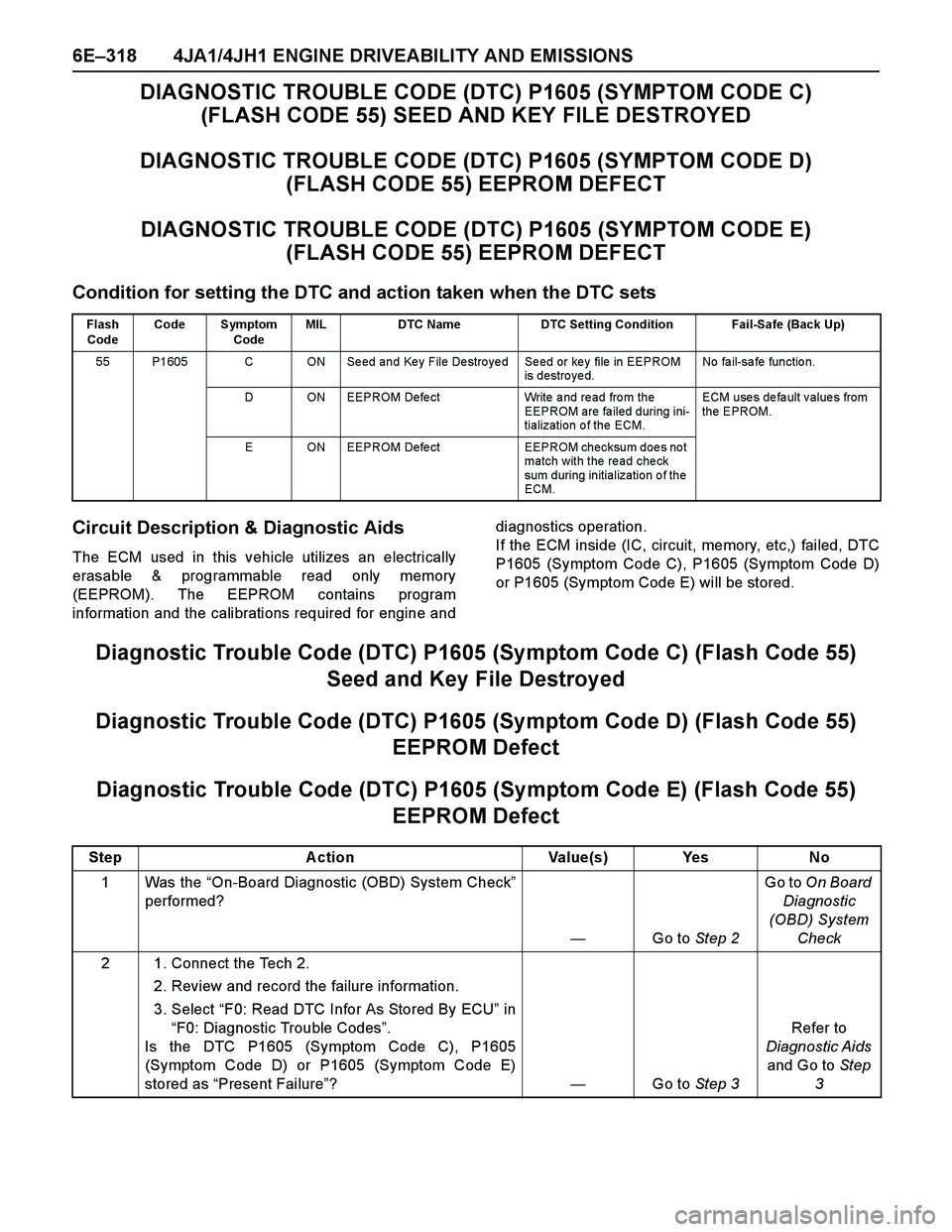
DIAGNOSTIC TROUBLE CODE (DTC) P1605 (SYMPTOM CODE C)
(FLASH CODE 55) SEED AND KEY FILE DESTROYED
DIAGNOSTIC TROUBLE CODE (DTC) P1605 (SYMPTOM CODE D)
(FLASH CODE 55) EEPROM DEFECT
DIAGNOSTIC TROUBLE CODE (DTC) P1605 (SYMPTOM CODE E)
(FLASH CODE 55) EEPROM DEFECT
Condition for setting the DTC and action taken when the DTC sets
Circuit Description & Diagnostic Aids
The ECM used in this vehicle utilizes an electrically
erasable & programmable read only memory
(EEPROM). The EEPROM contains program
information and the calibrations required for engine anddiagnostics operation.
If the ECM inside (IC, circuit, memory, etc,) failed, DTC
P1605 (Symptom Code C), P1605 (Symptom Code D)
or P1605 (Symptom Code E) will be stored.
Diagnostic Trouble Code (DTC) P1605 (Symptom Code C) (Flash Code 55)
Seed and Key File Destroyed
Diagnostic Trouble Code (DTC) P1605 (Symptom Code D) (Flash Code 55)
EEPROM Defect
Diagnostic Trouble Code (DTC) P1605 (Symptom Code E) (Flash Code 55)
EEPROM Defect
Flash
CodeCode Symptom
CodeMIL DTC Name DTC Setting Condition Fail-Safe (Back Up)
55 P1605 C ON Seed and Key File Destroyed Seed or key file in EEPROM
is destroyed.No fa il-sa fe fun ctio n.
D ON EEPROM Defe ct Write a nd re ad fro m the
EEPROM are fa iled during ini-
tialization of the ECM.ECM uses default values from
the EPROM.
E ON EEPROM Defe ct EEPROM checksum doe s no t
match with the read check
sum during initialization of the
ECM.
Step Action Value(s) Yes No
1Was the “On-Board Diagnostic (OBD) System Check”
performed?
—Go to Step 2Go to On Board
Diagnostic
(OBD) System
Check
2 1. Connect the Tech 2.
2. Review and record the failure information.
3. Select “F0: Read DTC Infor As Stored By ECU” in
“F0: Diagnostic Trouble Codes”.
Is the DTC P1605 (Symptom Code C), P1605
(Symptom Code D) or P1605 (Symptom Code E)
stored as “Present Failure”?—Go to Step 3Refer to
Diagnostic Aids
and Go to Step
3
Page 1692 of 4264
6E–320 4JA1/4JH1 ENGINE DRIVEABILITY AND EMISSIONS
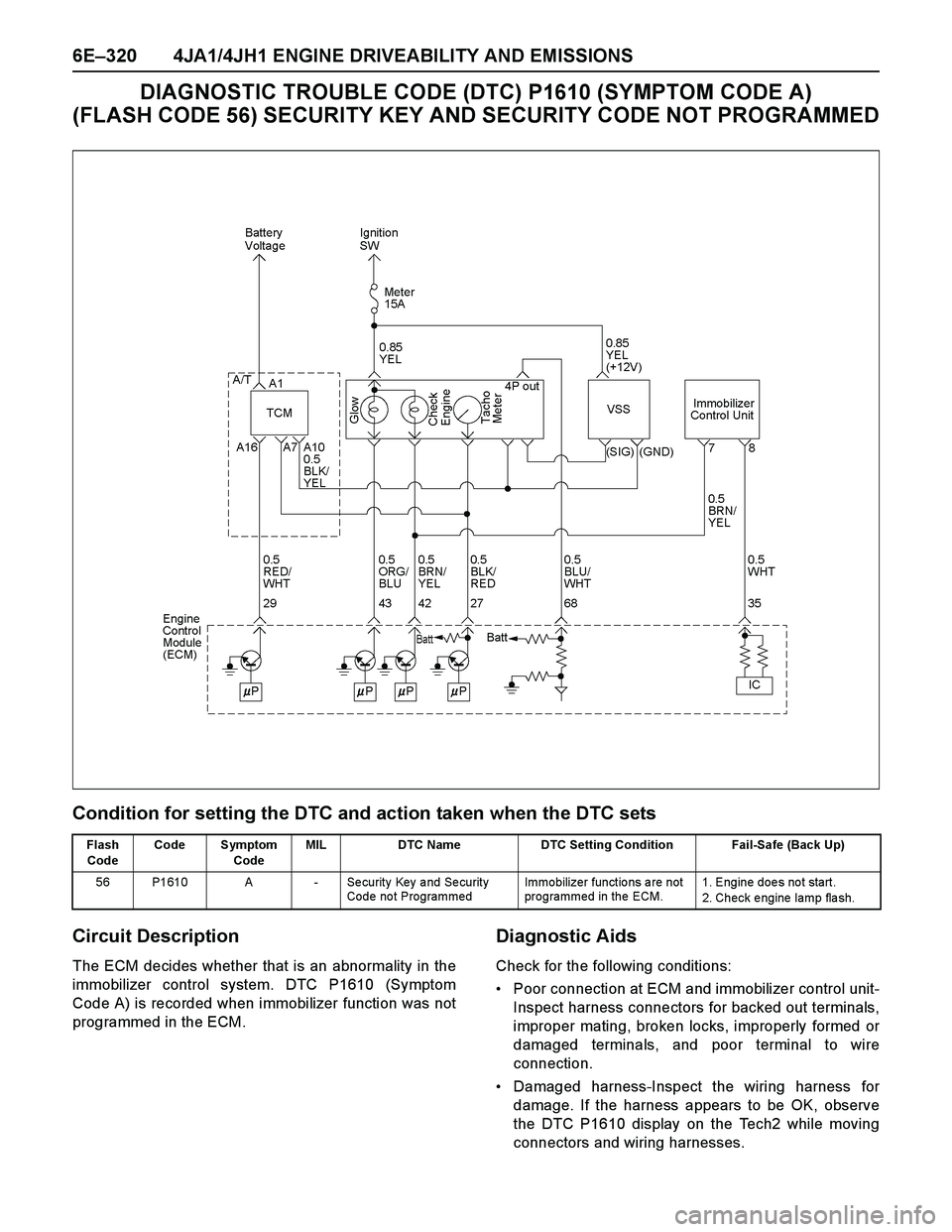
DIAGNOSTIC TROUBLE CODE (DTC) P1610 (SYMPTOM CODE A)
(FLASH CODE 56) SECURITY KEY AND SECURITY CODE NOT PROGRAMMED
Condition for setting the DTC and action taken when the DTC sets
Circuit Description
The ECM decides whether that is an abnormality in the
immobilizer control system. DTC P1610 (Symptom
Code A) is recorded when immobilizer function was not
programmed in the ECM.
Diagnostic Aids
Check for the following conditions:
Poor connection at ECM and immobilizer control unit-
Inspect harness connectors for backed out terminals,
improper mating, broken locks, improperly formed or
damaged terminals, and poor terminal to wire
connection.
Damaged harness-Inspect the wiring harness for
damage. If the harness appears to be OK, observe
the DTC P1610 display on the Tech2 while moving
connectors and wiring harnesses.
Flash
CodeCode Symptom
CodeMIL DTC Name DTC Setting Condition Fail-Safe (Back Up)
56 P1610 A - Security Key and Security
Code not ProgrammedImmobilizer functions are not
programmed in the ECM.1. Engine does not start.
2. Check e ngine lamp fla sh.
Page 1693 of 4264
4JA1/4JH1 ENGINE DRIVEABILITY AND EMISSIONS 6E–321
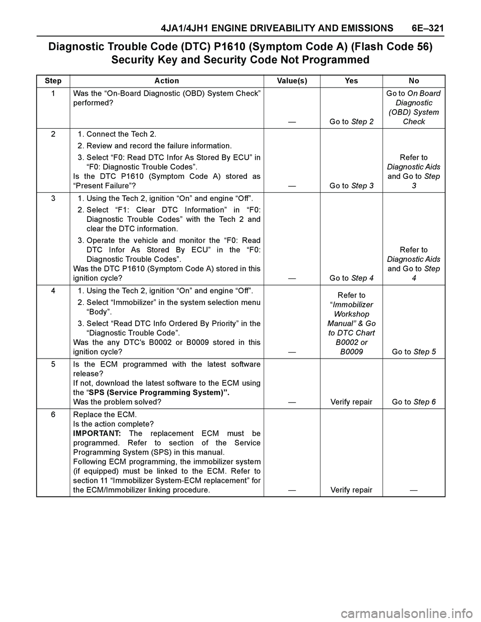
Diagnostic Trouble Code (DTC) P1610 (Symptom Code A) (Flash Code 56)
Security Key and Security Code Not Programmed
Step Action Value(s) Yes No
1Was the “On-Board Diagnostic (OBD) System Check”
performed?
—Go to Step 2Go to On Board
Diagnostic
(OBD) System
Check
2 1. Connect the Tech 2.
2. Review and record the failure information.
3. Select “F0: Read DTC Infor As Stored By ECU” in
“F0: Diagnostic Trouble Codes”.
Is the DTC P1610 (Symptom Code A) stored as
“Present Failure”?—Go to Step 3Refer to
Diagnostic Aids
and Go to Step
3
3 1. Using the Tech 2, ignition “On” and engine “Off”.
2. Select “F1: Clear DTC Information” in “F0:
Diagnostic Trouble Codes” with the Tech 2 and
clear the DTC information.
3. Operate the vehicle and monitor the “F0: Read
DTC Infor As Stored By ECU” in the “F0:
Diagnostic Trouble Codes”.
Was the DTC P1610 (Symptom Code A) stored in this
ignition cycle?—Go to Step 4Refer to
Diagnostic Aids
and Go to Step
4
4 1. Using the Tech 2, ignition “On” and engine “Off”.
2. Select “Immobilizer” in the system selection menu
“Body”.
3. Select “Read DTC Info Ordered By Priority” in the
“Diagnostic Trouble Code”.
Was the any DTC's B0002 or B0009 stored in this
ignition cycle?—Refer to
“Immobilizer
Workshop
Manual” & Go
to DTC Chart
B0002 or
B0009Go to Step 5
5 Is the ECM programmed with the latest software
release?
If not, download the latest software to the ECM using
the “SPS (Service Programming System)”.
Was the problem solved?—Verify repair Go to Step 6
6 Replace the ECM.
Is the action complete?
IMPORTANT: The replacement ECM must be
programmed. Refer to section of the Service
Programming System (SPS) in this manual.
Following ECM programming, the immobilizer system
(if equipped) must be linked to the ECM. Refer to
section 11 “Immobilizer System-ECM replacement” for
the ECM/Immobilizer linking procedure.—Verify repair—
Page 1707 of 4264
4JA1/4JH1 ENGINE DRIVEABILITY AND EMISSIONS 6E–335
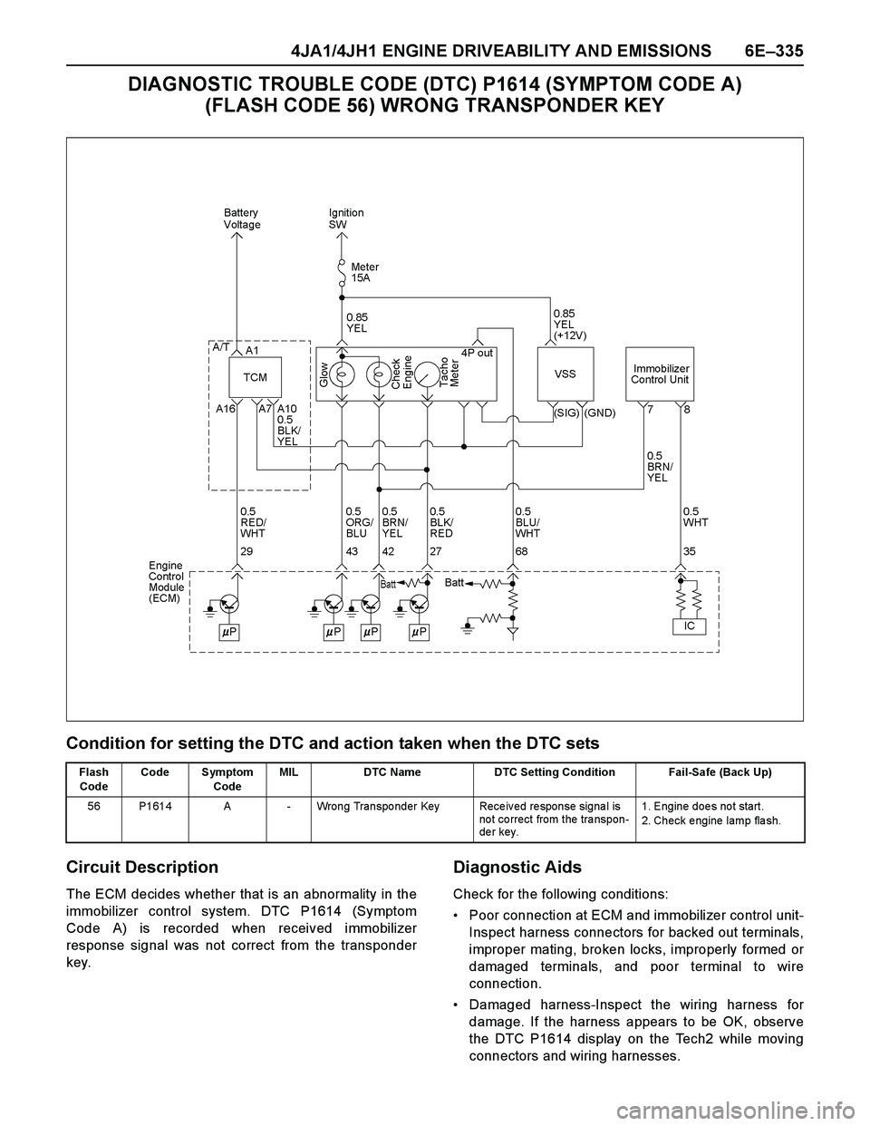
DIAGNOSTIC TROUBLE CODE (DTC) P1614 (SYMPTOM CODE A)
(FLASH CODE 56) WRONG TRANSPONDER KEY
Condition for setting the DTC and action taken when the DTC sets
Circuit Description
The ECM decides whether that is an abnormality in the
immobilizer control system. DTC P1614 (Symptom
Code A) is recorded when received immobilizer
response signal was not correct from the transponder
key.
Diagnostic Aids
Check for the following conditions:
Poor connection at ECM and immobilizer control unit-
Inspect harness connectors for backed out terminals,
improper mating, broken locks, improperly formed or
damaged terminals, and poor terminal to wire
connection.
Damaged harness-Inspect the wiring harness for
damage. If the harness appears to be OK, observe
the DTC P1614 display on the Tech2 while moving
connectors and wiring harnesses.
Flash
CodeCode Symptom
CodeMIL DTC Name DTC Setting Condition Fail-Safe (Back Up)
56 P1614 A - Wrong Transponder Key Received response signal is
not correct from the transpon-
der key.1. Engine does not start.
2. Check e ngine lamp fla sh.
Page 1708 of 4264
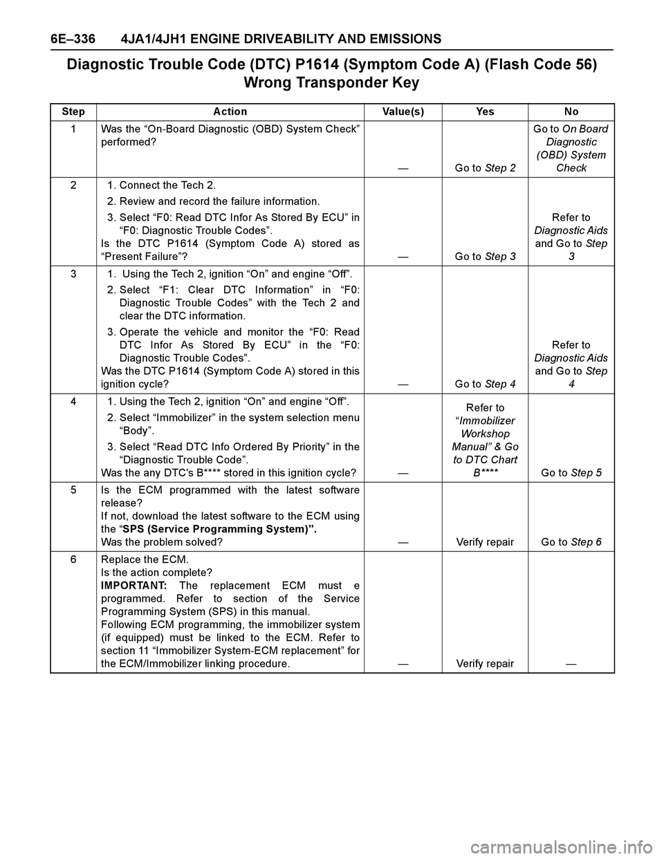
6E–336 4JA1/4JH1 ENGINE DRIVEABILITY AND EMISSIONS
Diagnostic Trouble Code (DTC) P1614 (Symptom Code A) (Flash Code 56)
Wrong Transponder Key
Step Action Value(s) Yes No
1Was the “On-Board Diagnostic (OBD) System Check”
performed?
—Go to Step 2Go to On Board
Diagnostic
(OBD) System
Check
2 1. Connect the Tech 2.
2. Review and record the failure information.
3. Select “F0: Read DTC Infor As Stored By ECU” in
“F0: Diagnostic Trouble Codes”.
Is the DTC P1614 (Symptom Code A) stored as
“Present Failure”?—Go to Step 3Refer to
Diagnostic Aids
and Go to Step
3
3 1. Using the Tech 2, ignition “On” and engine “Off”.
2. Select “F1: Clear DTC Information” in “F0:
Diagnostic Trouble Codes” with the Tech 2 and
clear the DTC information.
3. Operate the vehicle and monitor the “F0: Read
DTC Infor As Stored By ECU” in the “F0:
Diagnostic Trouble Codes”.
Was the DTC P1614 (Symptom Code A) stored in this
ignition cycle?—Go to Step 4Refer to
Diagnostic Aids
and Go to Step
4
4 1. Using the Tech 2, ignition “On” and engine “Off”.
2. Select “Immobilizer” in the system selection menu
“Body”.
3. Select “Read DTC Info Ordered By Priority” in the
“Diagnostic Trouble Code”.
Was the any DTC's B**** stored in this ignition cycle?—Refer to
“Immobilizer
Workshop
Manual” & Go
to DTC Chart
B**** Go to Step 5
5 Is the ECM programmed with the latest software
release?
If not, download the latest software to the ECM using
the “SPS (Service Programming System)”.
Was the problem solved?—Verify repair Go to Step 6
6 Replace the ECM.
Is the action complete?
IMPORTANT: The replacement ECM must e
programmed. Refer to section of the Service
Programming System (SPS) in this manual.
Following ECM programming, the immobilizer system
(if equipped) must be linked to the ECM. Refer to
section 11 “Immobilizer System-ECM replacement” for
the ECM/Immobilizer linking procedure.—Verify repair—
Page 1951 of 4264
ENGINE FUEL (6VE1 3.5L) 6C-9
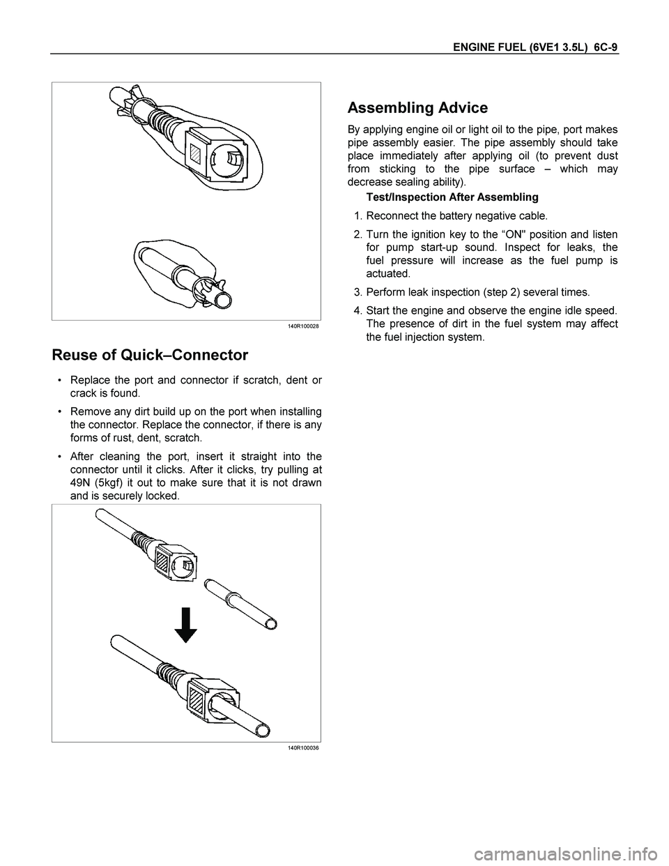
140R100028
Reuse of Quick–Connector
Replace the port and connector if scratch, dent or
crack is found.
Remove any dirt build up on the port when installing
the connector. Replace the connector, if there is any
forms of rust, dent, scratch.
After cleaning the port, insert it straight into the
connector until it clicks. After it clicks, try pulling a
t
49N (5kgf) it out to make sure that it is not drawn
and is securely locked.
140R100036
Assembling Advice
By applying engine oil or light oil to the pipe, port makes
pipe assembly easier. The pipe assembly should take
place immediately after applying oil (to prevent dus
t
from sticking to the pipe surface –which may
decrease sealing ability).
Test/Inspection After Assembling
1. Reconnect the battery negative cable.
2. Turn the ignition key to the “ON" position and listen
for pump start-up sound. Inspect for leaks, the
fuel pressure will increase as the fuel pump is
actuated.
3. Perform leak inspection (step 2) several times.
4. Start the engine and observe the engine idle speed.
The presence of dirt in the fuel system may affec
t
the fuel injection system.
Page 1997 of 4264
3.5L ENGINE DRIVEABILITY AND EMISSIONS 6E-1
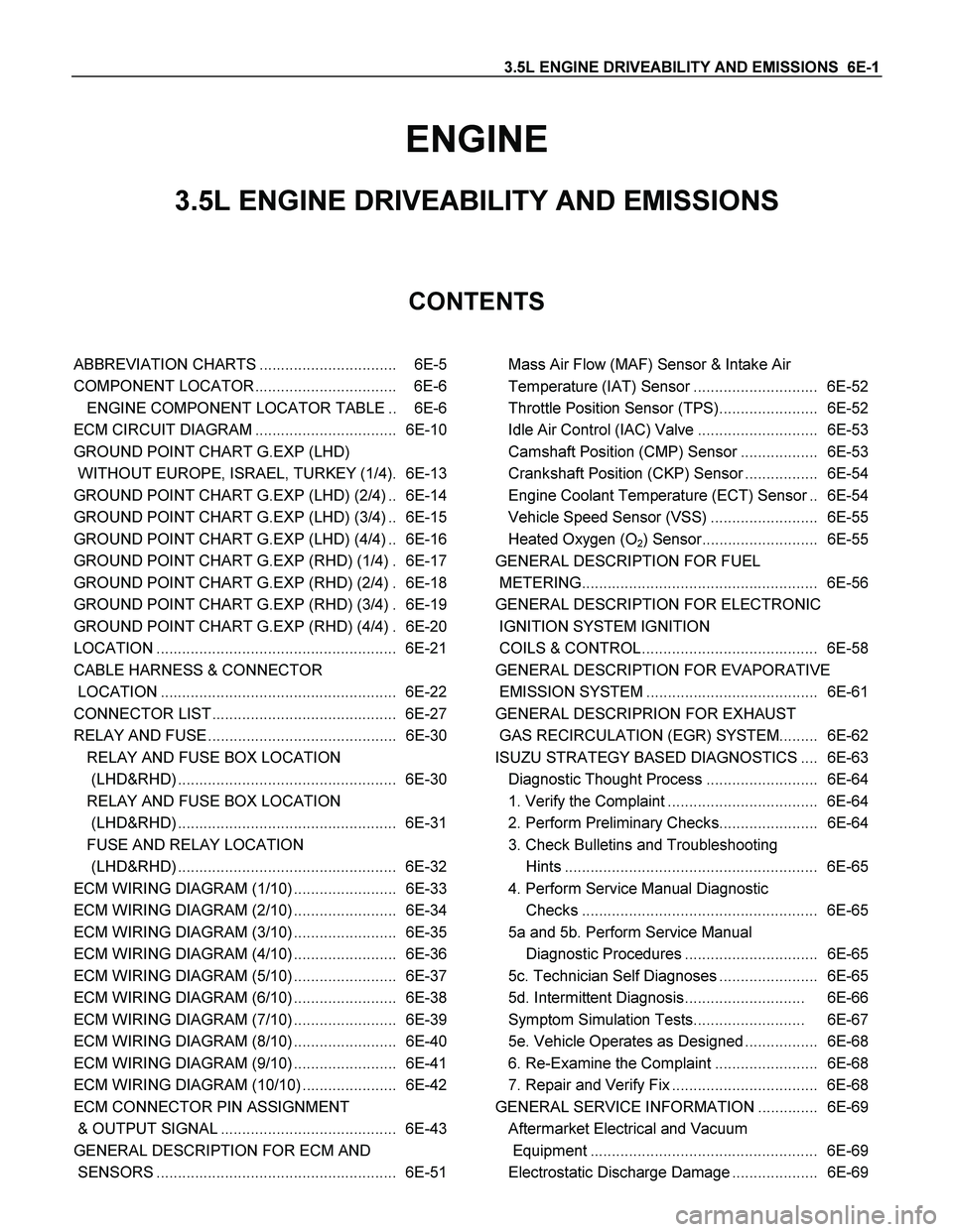
ENGINE
3.5L ENGINE DRIVEABILITY AND EMISSIONS
CONTENTS
ABBREVIATION CHARTS ................................ 6E-5
COMPONENT LOCATOR ................................. 6E-6
ENGINE COMPONENT LOCATOR TABLE .. 6E-6
ECM CIRCUIT DIAGRAM ................................. 6E-10
GROUND POINT CHART G.EXP (LHD)
WITHOUT EUROPE, ISRAEL, TURKEY (1/4). 6E-13
GROUND POINT CHART G.EXP (LHD) (2/4) .. 6E-14
GROUND POINT CHART G.EXP (LHD) (3/4) .. 6E-15
GROUND POINT CHART G.EXP (LHD) (4/4) .. 6E-16
GROUND POINT CHART G.EXP (RHD) (1/4) . 6E-17
GROUND POINT CHART G.EXP (RHD) (2/4) . 6E-18
GROUND POINT CHART G.EXP (RHD) (3/4) . 6E-19
GROUND POINT CHART G.EXP (RHD) (4/4) . 6E-20
LOCATION ........................................................ 6E-21
CABLE HARNESS & CONNECTOR
LOCATION ....................................................... 6E-22
CONNECTOR LIST ........................................... 6E-27
RELAY AND FUSE ............................................ 6E-30
RELAY AND FUSE BOX LOCATION
(LHD&RHD) ................................................... 6E-30
RELAY AND FUSE BOX LOCATION
(LHD&RHD) ................................................... 6E-31
FUSE AND RELAY LOCATION
(LHD&RHD) ................................................... 6E-32
ECM WIRING DIAGRAM (1/10) ........................ 6E-33
ECM WIRING DIAGRAM (2/10) ........................ 6E-34
ECM WIRING DIAGRAM (3/10) ........................ 6E-35
ECM WIRING DIAGRAM (4/10) ........................ 6E-36
ECM WIRING DIAGRAM (5/10) ........................ 6E-37
ECM WIRING DIAGRAM (6/10) ........................ 6E-38
ECM WIRING DIAGRAM (7/10) ........................ 6E-39
ECM WIRING DIAGRAM (8/10) ........................ 6E-40
ECM WIRING DIAGRAM (9/10) ........................ 6E-41
ECM WIRING DIAGRAM (10/10) ...................... 6E-42
ECM CONNECTOR PIN ASSIGNMENT
& OUTPUT SIGNAL ......................................... 6E-43
GENERAL DESCRIPTION FOR ECM AND
SENSORS ........................................................ 6E-51
Mass Air Flow (MAF) Sensor & Intake Air
Temperature (IAT) Sensor ............................. 6E-52
Throttle Position Sensor (TPS)....................... 6E-52
Idle Air Control (IAC) Valve ............................ 6E-53
Camshaft Position (CMP) Sensor .................. 6E-53
Crankshaft Position (CKP) Sensor ................. 6E-54
Engine Coolant Temperature (ECT) Sensor .. 6E-54
Vehicle Speed Sensor (VSS) ......................... 6E-55
Heated Oxygen (O
2) Sensor........................... 6E-55
GENERAL DESCRIPTION FOR FUEL
METERING....................................................... 6E-56
GENERAL DESCRIPTION FOR ELECTRONIC
IGNITION SYSTEM IGNITION
COILS & CONTROL ......................................... 6E-58
GENERAL DESCRIPTION FOR EVAPORATIVE
EMISSION SYSTEM ........................................ 6E-61
GENERAL DESCRIPRION FOR EXHAUST
GAS RECIRCULATION (EGR) SYSTEM......... 6E-62
ISUZU STRATEGY BASED DIAGNOSTICS .... 6E-63
Diagnostic Thought Process .......................... 6E-64
1. Verify the Complaint ................................... 6E-64
2. Perform Preliminary Checks....................... 6E-64
3. Check Bulletins and Troubleshooting
Hints ........................................................... 6E-65
4. Perform Service Manual Diagnostic
Checks ....................................................... 6E-65
5a and 5b. Perform Service Manual
Diagnostic Procedures ............................... 6E-65
5c. Technician Self Diagnoses ....................... 6E-65
5d. Intermittent Diagnosis............................ 6E-66
Symptom Simulation Tests.......................... 6E-67
5e. Vehicle Operates as Designed ................. 6E-68
6. Re-Examine the Complaint ........................ 6E-68
7. Repair and Verify Fix .................................. 6E-68
GENERAL SERVICE INFORMATION .............. 6E-69
Aftermarket Electrical and Vacuum
Equipment ..................................................... 6E-69
Electrostatic Discharge Damage .................... 6E-69
Page 2039 of 4264
3.5L ENGINE DRIVEABILITY AND EMISSIONS 6E-43
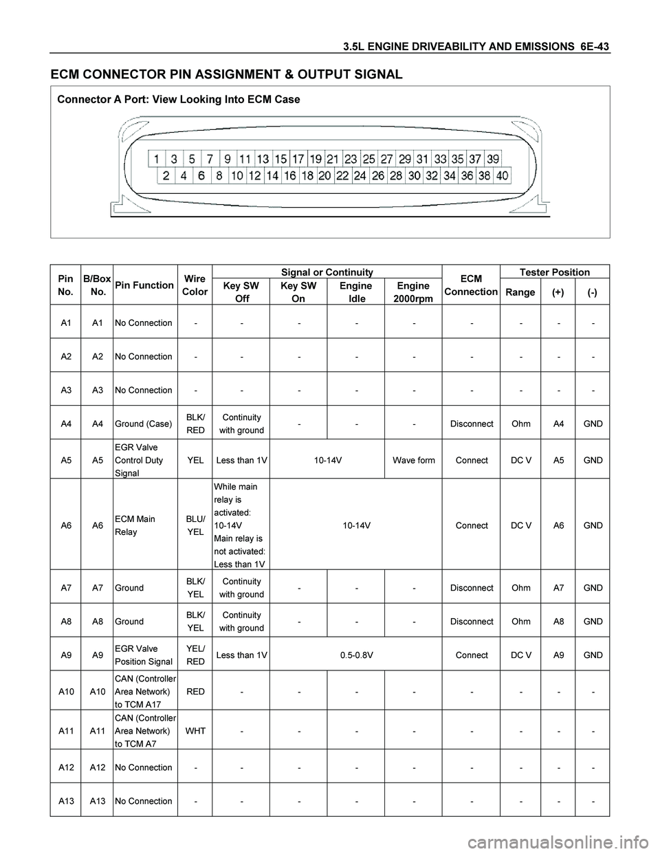
ECM CONNECTOR PIN ASSIGNMENT & OUTPUT SIGNAL
Connector A Port: View Looking Into ECM Case
Signal or Continuity Tester Position Pin
No.
B/Box
No.
Pin Function Wire
Color
Key SW
Off Key SW
On Engine
Idle Engine
2000rpmECM
Connection Range(+) (-)
A1 A1 No Connection - - - - - - - - -
A2 A2 No Connection - - - - - - - - -
A3 A3 No Connection - - - - - - - - -
A4 A4 Ground (Case) BLK/
RED Continuity
with ground - - - Disconnect Ohm A4 GND
A5 A5 EGR Valve
Control Duty
Signal YEL Less than 1V 10-14V Wave form Connect DC V A5 GND
A6 A6 ECM Main
Relay BLU/
YEL While main
relay is
activated:
10-14V
Main relay is
not activated:
Less than 1V 10-14V Connect DC V A6 GND
A7 A7 Ground BLK/
YEL Continuity
with ground - - - Disconnect Ohm A7 GND
A8 A8 Ground BLK/
YEL Continuity
with ground - - - Disconnect Ohm A8 GND
A9 A9 EGR Valve
Position Signal YEL/
RED Less than 1V 0.5-0.8V Connect DC V A9 GND
A10 A10 CAN (Controller
Area Network)
to TCM A17 RED - - - - - - - -
A11 A11 CAN (Controller
Area Network)
to TCM A7 WHT - - - - - - - -
A12 A12 No Connection - - - - - - - - -
A13 A13 No Connection - - - - - - - - -