2004 ISUZU TF SERIES key
[x] Cancel search: keyPage 1433 of 4264
4JA1/4JH1 ENGINE DRIVEABILITY AND EMISSIONS 6E–61
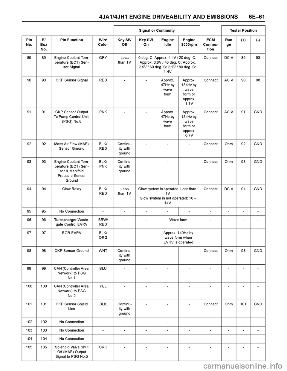
89 89 Engine Coolant Tem-
perature (ECT) Sen-
sor Signa lGRY Le ss
tha n 1V0 deg. C: Approx. 4.4V / 20 deg. C:
Approx. 3.8V / 40 deg. C: Approx.
2.9V / 60 deg. C: 2.1V / 80 deg. C:
1.4VCo nnect DC V 89 93
90 90 CKP Senso r Signal RED - - Approx .
47Hz by
wave
form Approx.
134Hz by
wave
fo rm or
approx.
1.1VCo nnect AC V 90 98
91 91 CKP Sensor Output
To Pump Contro l Unit
(PSG) No.8PNK - - Approx .
47Hz by
wave
form Approx.
134Hz by
wave
fo rm or
approx.
0.7VCo nnect AC V 91 GND
92 92 Ma ss Air Flow (MAF)
Se nso r Gro undBLK/
REDCo ntinu-
ity with
ground- - - Connect Ohm 92 GND
93 93 Engine Coolant Tem-
perature (ECT) Sen-
so r & Ma nifo ld
Pressure Sensor
GroundBLK/
PNKCo ntinu-
ity with
ground- - - Connect Ohm 93 GND
94 94 Glo w Re la y BLK/
REDLe ss
tha n 1VGlow system is operated: Less than
1 V
Glow system is not operated: 10 -
14VCo nnect DC V 94 GND
9595No Connection---------
96 96 Turbo charge r Wa ste-
ga te Contro l EVRVBRW/
RED- - Wav e form - - - -
97 97 EGR EVRV BLK/
ORG- - Appro x. 140Hz by
wa ve fo rm whe n
EVRV is operated- ---
98 98 CKP Se nso r Ground WHT Co ntinu-
ity with
ground- - - Connect Ohm 98 GND
99 99 CAN (Contro lle r Area
Ne two rk) to PSG
No .1BLU--------
100 100 CAN (Contro lle r Area
Ne two rk) to PSG
No .2YEL--------
101 101 CKP Senso r Shie ld
LineBLK Co ntinu-
ity with
ground- - - Connect Ohm 101 GND
102102No Connection---------
103103No Connection---------
104104No Connection---------
105 105 Solenoid Valve Shut
Off (MAB) Output
Signa l to PSG No .5ORG --------Signal or Continuity Tester Position
Pin
No. B/
Box
No.Pin Function Wire
ColorKey SW
OffKey SW
OnEngine
IdleEngine
2000rpmECM
Connec-
tionRan
ge(+) (-)
Page 1434 of 4264
6E–62 4JA1/4JH1 ENGINE DRIVEABILITY AND EMISSIONS
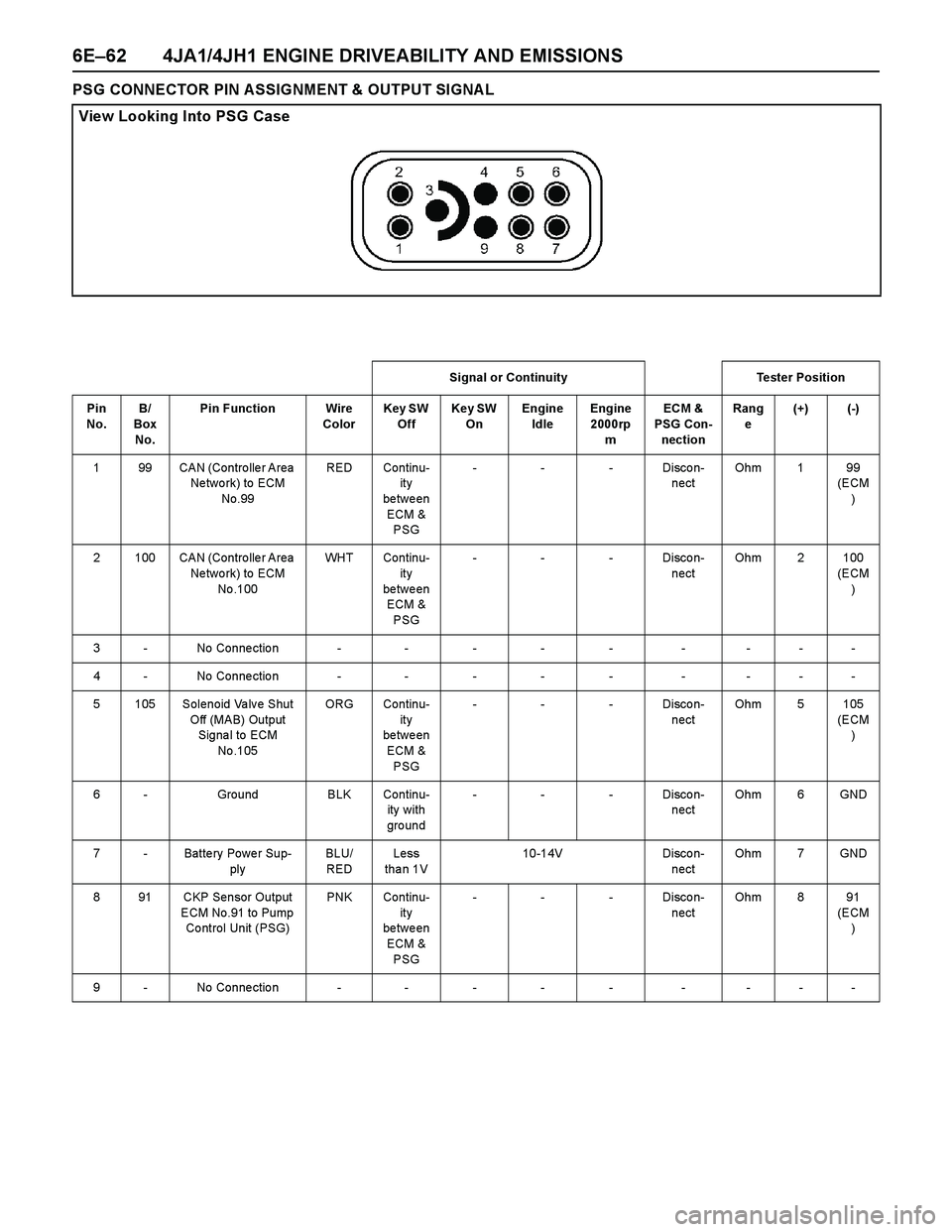
PSG CONNECTOR PIN ASSIGNMENT & OUTPUT SIGNAL
View Looking Into PSG Case
Signal or Continuity Tester Position
Pin
No. B/
Box
No.Pin Function Wire
ColorKey SW
OffKey SW
OnEngine
IdleEngine
2000rp
mECM &
PSG Con-
nectionRang
e(+) (-)
1 99 CAN (Contro lle r Area
Ne two rk) to ECM
No.99RED Continu-
ity
between
ECM &
PSG- - - Disco n-
nectOhm 1 99
(ECM
)
2 100 CAN (Contro lle r Area
Ne two rk) to ECM
No .100WHT Continu-
ity
between
ECM &
PSG- - - Disco n-
nectOhm 2 100
(ECM
)
3 - No Connection - - - - - - - - -
4 - No Connection - - - - - - - - -
5 105 Solenoid Valve Shut
Off (MAB) Output
Signa l to ECM
No .105ORG Continu-
ity
between
ECM &
PSG- - - Disco n-
nectOhm 5 105
(ECM
)
6 - Ground BLK Continu-
ity with
gro und- - - Disco n-
nectOhm 6 GND
7 - Batte ry Powe r Sup-
plyBLU/
REDLess
tha n 1V10-14V Disco n-
nectOhm 7 GND
8 91 CKP Sensor Output
ECM No.91 to Pump
Co ntrol Unit (PSG)PNK Continu-
ity
between
ECM &
PSG- - - Disco n-
nectOhm 8 91
(ECM
)
9 - No Connection - - - - - - - - -
Page 1457 of 4264
4JA1/4JH1 ENGINE DRIVEABILITY AND EMISSIONS 6E–85
DIAGNOSIS WITH Tech 2
If no codes are set:
Refer to F1: Data Display and identify the electrical
faults that are not indicated by trouble code.
Refer to “SYMPTOM DIAGNOSIS”.
If codes are set:
1. Record all trouble codes displayed by Tech 2 and
check id the codes are intermittent.
2. Clear the codes.
3. Drive the vehicle for a test to reproduce the faulty
status.
4. Check trouble codes again using the Tech 2.
5. If no codes is displayed by test driving, the fault is
intermittent. In this case, refer to “DIAGNOSIS
AIDS”.
6. If a code is present, refer to DTC Chart for
diagnosis.
7. Check trouble codes again using the Tech 2.
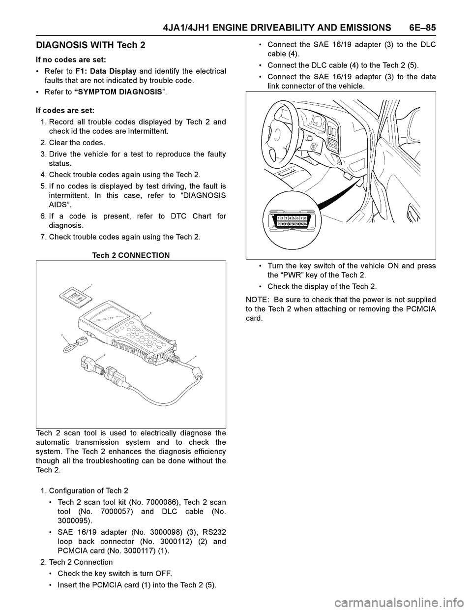
Tech 2 CONNECTION
Tech 2 scan tool is used to electrically diagnose the
automatic transmission system and to check the
system. The Tech 2 enhances the diagnosis efficiency
though all the troubleshooting can be done without the
Te c h 2 .
1. Configuration of Tech 2
Tech 2 scan tool kit (No. 7000086), Tech 2 scan
tool (No. 7000057) and DLC cable (No.
3000095).
SAE 16/19 adapter (No. 3000098) (3), RS232
loop back connector (No. 3000112) (2) and
PCMCIA card (No. 3000117) (1).
2. Tech 2 Connection
Check the key switch is turn OFF.
Insert the PCMCIA card (1) into the Tech 2 (5).Connect the SAE 16/19 adapter (3) to the DLC
cable (4).
Connect the DLC cable (4) to the Tech 2 (5).
Connect the SAE 16/19 adapter (3) to the data
link connector of the vehicle.
Turn the key switch of the vehicle ON and press
the “PWR” key of the Tech 2.
Check the display of the Tech 2.
NOTE: Be sure to check that the power is not supplied
to the Tech 2 when attaching or removing the PCMCIA
card.
Page 1458 of 4264
6E–86 4JA1/4JH1 ENGINE DRIVEABILITY AND EMISSIONS
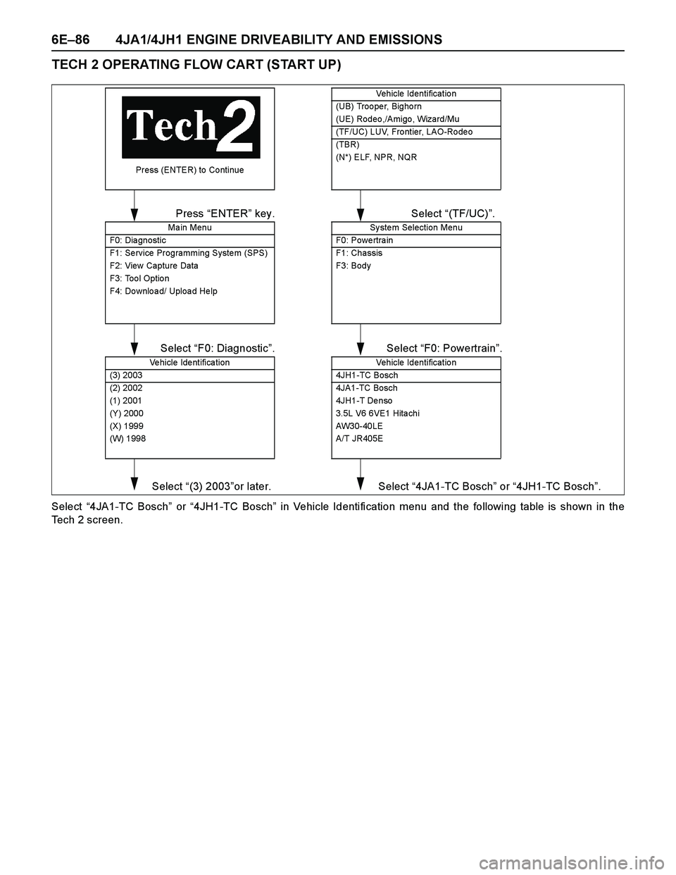
TECH 2 OPERATING FLOW CART (START UP)
Select “4JA1-TC Bosch” or “4JH1-TC Bosch” in Vehicle Identification menu and the following table is shown in the
Tech 2 screen.
Press (ENTER) to Co ntinue
Main Menu
F0: Dia gnostic
F1: Se rvice Programming Syste m (SPS)
F2: View Capture Data
F3: Too l Optio n
F4: Do wnlo a d/ Uploa d He lp
Press “ENTER” key.
Ve hi cl e Ide nt ifi ca ti o n
(3) 2003
(2) 2002
(1) 2001
(Y) 2000
(X) 1999
(W) 1998
Select “F0: Diagnostic”.
Select “(3) 2003”or later.
System Selection Menu
F0: Powe rtra in
F1: Chassis
F3: Body
Select “(TF/UC)”.
Vehicle Identification
4JH1-TC Bosch
4JA1-TC Bosch
4JH1-T Denso
3.5L V6 6VE1 Hita chi
AW30-40LE
A/T JR405E
Select “F0: Powertrain”.
Select “4JA1-TC Bosch” or “4JH1-TC Bosch”.
Vehicle Identification
(UB) Troo pe r, Bigho rn
(UE) Rodeo,/Amigo, Wizard/Mu
(TF/UC) LUV, Fro ntier, LAO-Ro de o
(TBR)
(N*) ELF, NPR, NQR
Page 1460 of 4264
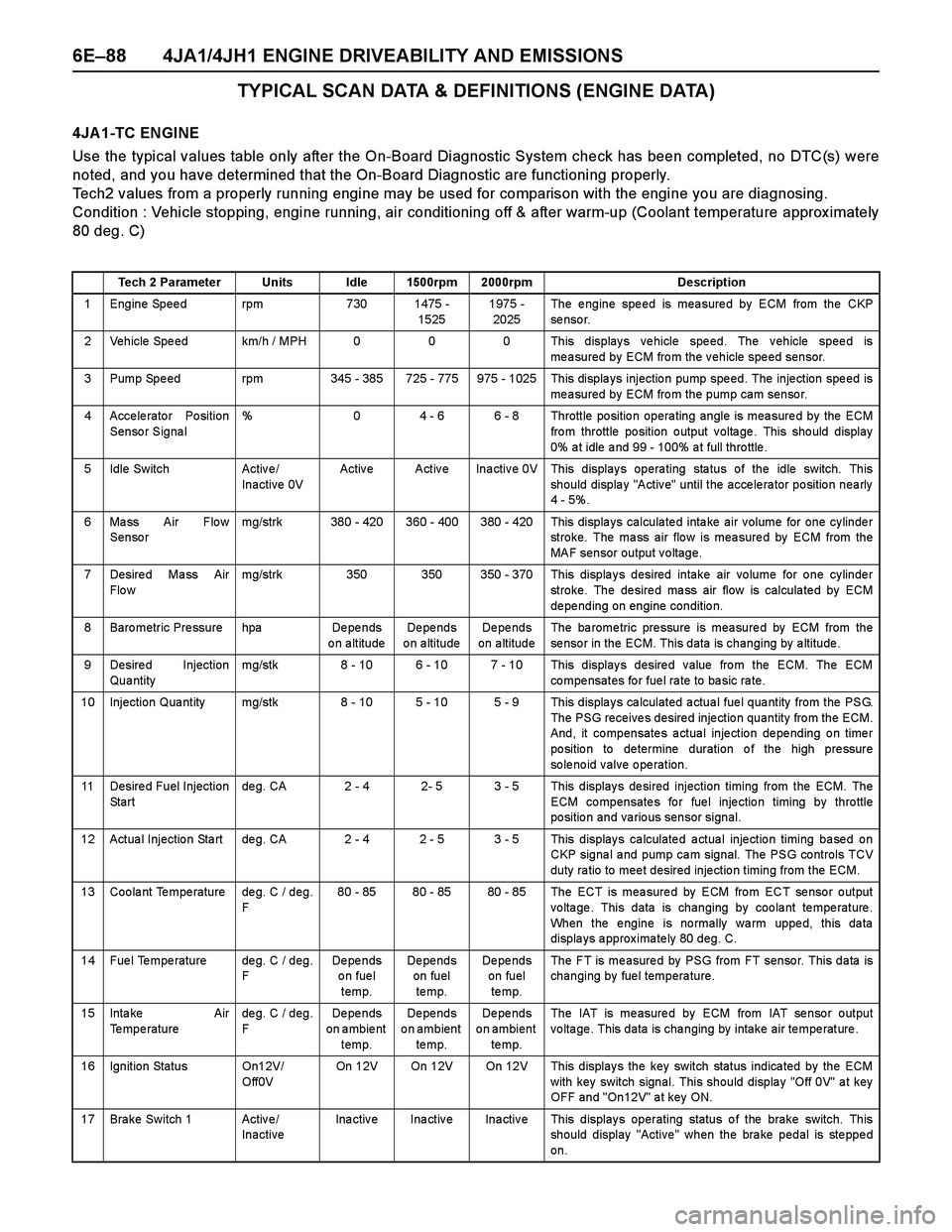
6E–88 4JA1/4JH1 ENGINE DRIVEABILITY AND EMISSIONS
TYPICAL SCAN DATA & DEFINITIONS (ENGINE DATA)
4JA 1-TC ENGINE
Use the typical values table only after the On-Board Diagnostic System check has been completed, no DTC(s) were
noted, and you have determined that the On-Board Diagnostic are functioning properly.
Tech2 values from a properly running engine may be used for comparison with the engine you are diagnosing.
Condition : Vehicle stopping, engine running, air conditioning off & after warm-up (Coolant temperature approx imately
80 deg. C)
Tech 2 Parameter Units Idle 1500rpm 2000rpm Description
1 Engine Speed rpm 730 1475 -
15251975 -
2025The engine speed is measured by ECM from the CKP
se nso r.
2 Vehicle Speed km/h / MPH 0 0 0 This displays vehicle speed. The vehicle speed is
measured by ECM from the vehicle speed sensor.
3 Pump Spe ed rpm 345 - 385 725 - 775 975 - 1025 This displa ys injectio n pump spe ed. The inje ction spe ed is
measured by ECM from the pump cam sensor.
4 Accelerator Position
Sensor Signal% 0 4 - 6 6 - 8 Throttle position operating angle is measured by the ECM
fro m throttle po sition o utput v olta ge . This sho uld display
0% a t idle a nd 99 - 100% a t full thro ttle .
5 Idle Switch Activ e /
Inactive 0VActive Active Inactive 0V This displays operating status of the idle switch. This
should display "Active" until the accelerator position nearly
4 - 5%.
6 Mass Air Flow
Sensormg/strk 380 - 420 360 - 400 380 - 420 This displays calculated intake air volume for one cylinder
stroke. The mass air flow is measured by ECM from the
MAF sensor output voltage.
7 Desire d Ma ss Air
Flo wmg/strk 350 350 350 - 370 This displays desired intake air volume for one cylinder
stroke. The desired mass air flow is calculated by ECM
de pe nding on engine conditio n.
8 Baro metric Pre ssure hpa De pe nds
on altitudeDe pe nds
o n a ltitudeDe pe nds
on altitudeThe ba rome tric pre ssure is mea sure d by ECM from the
sensor in the ECM. This data is changing by altitude.
9 Desired Injection
Qua ntitymg/stk 8 - 10 6 - 10 7 - 10 This displays desired value from the ECM. The ECM
co mpe nsates fo r fue l ra te to ba sic ra te.
10 Injection Qua ntity mg/stk 8 - 10 5 - 10 5 - 9 This displa y s ca lculated a ctua l fue l qua ntity from the PSG.
The PSG receives desired injection quantity from the ECM.
And, it compensates actual injection depending on timer
po sitio n to de termine duration o f the high pre ssure
solenoid valve operation.
11 Desire d Fuel Injection
St a r tde g. CA 2 - 4 2- 5 3 - 5 This display s de sired injection timing from the ECM. The
ECM compensates for fuel injection timing by throttle
position and various sensor signal.
12 Actua l Injectio n Sta rt de g. CA 2 - 4 2 - 5 3 - 5 This display s ca lculate d a ctua l inje ctio n timing ba se d o n
CKP signa l a nd pump ca m signal. The PSG controls TCV
duty ra tio to mee t desired inje ctio n timing from the ECM.
13 Coolant Temperature deg. C / deg.
F80 - 85 80 - 85 80 - 85 The ECT is measured by ECM from ECT sensor output
voltage. This data is changing by coolant temperature.
When the engine is normally warm upped, this data
displays approximately 80 deg. C.
14 Fuel Temperature deg. C / deg.
FDe pe nds
on fuel
temp.De pe nds
on fuel
te mp.De pe nds
on fuel
te mp.The FT is measured by PSG from FT sensor. This data is
changing by fuel temperature.
15 Inta ke Air
Temperaturedeg. C / deg.
FDe pe nds
on ambient
temp.De pe nds
on ambient
te mp.De pe nds
on ambient
te mp.The IAT is measured by ECM from IAT sensor output
voltage. This data is changing by intake air temperature.
16 Ignition Status On12V/
Off0VOn 12V On 12V On 12V This displays the key switch status indicated by the ECM
with key switch signal. This should display "Off 0V" at key
OFF and "On12V" at key ON.
17 Brake Switch 1 Active/
InactiveInactive Inactive Inactive This displays operating status of the brake switch. This
should display "Active" when the brake pedal is stepped
on.
Page 1461 of 4264
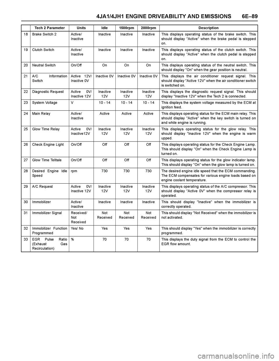
4JA1/4JH1 ENGINE DRIVEABILITY AND EMISSIONS 6E–89
18 Brake Switch 2 Active/
InactiveInactive Inactive Inactive This displays operating status of the brake switch. This
should display "Active" when the brake pedal is stepped
on.
19 Clutch Sw itch Activ e /
InactiveInactive Inactive Inactive This displays operating status of the clutch switch. This
should display "Active" when the clutch pedal is stepped
on.
20 Neutra l Switch On/Off On On On This displa ys o pe rating status of the neutra l switch. This
should display "On" when the gear position is neutral.
21 A/C Informa tion
SwitchActive 12V/
Inactive 0VInactive 0V Inactive 0V Inactive 0V This displays the air conditioner request signal. This
should display "Active 12V" when the air conditioner switch
is switched on.
22 Dia gnostic Re quest Activ e 0V/
Inactive 12VIna ctiv e
12VInactive
12VIna ctiv e
12VThis display s the dia gnostic reque st signal. This sho uld
display "Inactive 12V" when the Tech 2 is connected.
23 System Voltage V 10 - 14 10 - 14 10 - 14 This displays the system voltage measured by the ECM at
ignition feed.
24 Ma in Re la y Activ e /
InactiveActive Active Active This displays operating status for the ECM main relay. This
should display "Active" when the key switch is turned on
and while engine is running.
25 Glow Time Relay Activ e 0V/
Inactive12VIna ctiv e
12VInactive
12VIna ctiv e
12VThis displays operating status for the glow relay. This
should display "Inactive 12V" when the engine is warm
uppe d.
26 Check Engine Light On/Off Off Off Off This displays operating status for the Check Engine Lamp.
This should display "On" when the Check Engine Lamp is
turned on.
27 Glow Time Telltale On/Off Off Off Off This displays operating status for the glow indicator lamp.
This sho uld display "On" whe n the glo w la mp is turne d o n.
28 Desired Engine Idle
Speedrpm 730 730 730 The desired engine idle speed that the ECM commanding.
The ECM compensates for various engine loads based on
engine coolant temperature.
29 A/C Re que st Activ e 0V/
Inactive 12VIna ctiv e
12VInactive
12VIna ctiv e
12VThis displays operating status of the A/C compressor. This
should display "Active 0V" when the compressor relay is
operated.
30 Immo bilize r Activ e /
InactiveInactive Inactive Inactive This should display "Inactive" when the immobilizer is
correctly operated.
31 Immo bilize r Signal Rece iv ed/
Not
Rece iv edNo t
Receive dNo t
Re ceive dNot
Re ce iv e dThis sho uld displa y "No t Receive d" whe n the immo bilize r is
not activated.
32 Immo bilize r Function
ProgrammedYes/ No Yes Yes Yes This should display "Yes" when the immobilizer is correctly
programmed.
33 EGR Pulse Ratio
(Ex ha ust Ga s
Recirculatio n)% 70 70 70 This displays the duty signal from the ECM to control the
EGR flow amount. Tech 2 Parameter Units Idle 1500rpm 2000rpm Description
Page 1462 of 4264
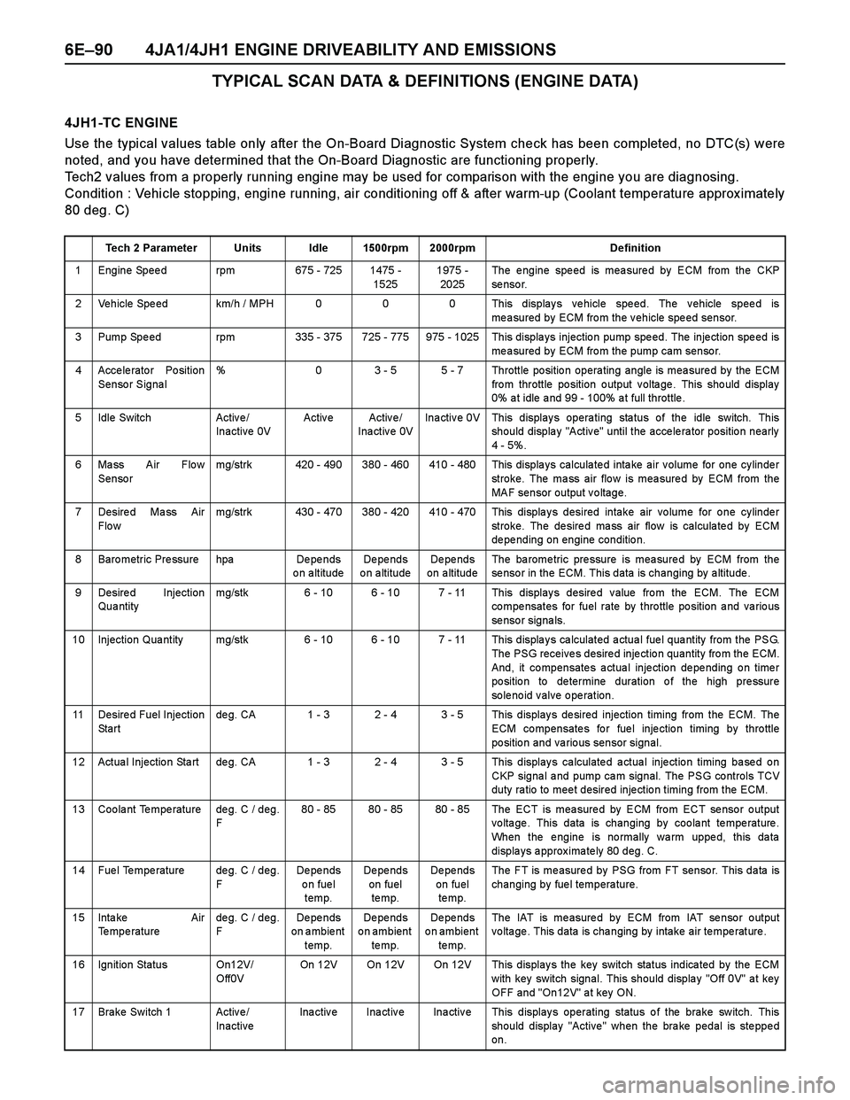
6E–90 4JA1/4JH1 ENGINE DRIVEABILITY AND EMISSIONS
TYPICAL SCAN DATA & DEFINITIONS (ENGINE DATA)
4JH1-TC ENGINE
Use the typical values table only after the On-Board Diagnostic System check has been completed, no DTC(s) were
noted, and you have determined that the On-Board Diagnostic are functioning properly.
Tech2 values from a properly running engine may be used for comparison with the engine you are diagnosing.
Condition : Vehicle stopping, engine running, air conditioning off & after warm-up (Coolant temperature approx imately
80 deg. C)
Tech 2 Parameter Units Idle 1500rpm 2000rpm Definition
1 Engine Speed rpm 675 - 725 1475 -
15251975 -
2025The engine speed is measured by ECM from the CKP
se nso r.
2 Vehicle Speed km/h / MPH 0 0 0 This displays vehicle speed. The vehicle speed is
measured by ECM from the vehicle speed sensor.
3 Pump Spe ed rpm 335 - 375 725 - 775 975 - 1025 This displa ys injectio n pump spe ed. The inje ction spe ed is
measured by ECM from the pump cam sensor.
4 Accelerator Position
Sensor Signal% 0 3 - 5 5 - 7 Throttle position operating angle is measured by the ECM
fro m throttle po sition o utput v olta ge . This sho uld display
0% a t idle a nd 99 - 100% a t full throttle .
5 Idle Switch Activ e /
Inactive 0VActive Active/
Inactive 0VInactive 0V This displays operating status of the idle switch. This
should display "Active" until the accelerator position nearly
4 - 5%.
6 Mass Air Flow
Sensormg/strk 420 - 490 380 - 460 410 - 480 This displays calculated intake air volume for one cylinder
stroke. The mass air flow is measured by ECM from the
MAF sensor output voltage.
7 Desire d Ma ss Air
Flo wmg/strk 430 - 470 380 - 420 410 - 470 This displays desired intake air volume for one cylinder
stroke. The desired mass air flow is calculated by ECM
de pe nding on engine conditio n.
8 Baro metric Pre ssure hpa De pe nds
on altitudeDe pe nds
o n a ltitudeDe pe nds
on altitudeThe ba rome tric pre ssure is mea sure d by ECM from the
sensor in the ECM. This data is changing by altitude.
9 Desired Injection
Qua ntitymg/stk 6 - 10 6 - 10 7 - 11 This displays desired value from the ECM. The ECM
co mpe nsates for fuel rate by thro ttle po sition a nd va rio us
se nso r signa ls.
10 Injection Qua ntity mg/stk 6 - 10 6 - 10 7 - 11 This displa y s ca lculated a ctua l fue l qua ntity from the PSG.
The PSG receives desired injection quantity from the ECM.
And, it compensates actual injection depending on timer
po sitio n to de termine duration o f the high pre ssure
solenoid valve operation.
11 Desire d Fuel Injection
St a r tde g. CA 1 - 3 2 - 4 3 - 5 This display s de sired injection timing from the ECM. The
ECM compensates for fuel injection timing by throttle
position and various sensor signal.
12 Actua l Injectio n Sta rt de g. CA 1 - 3 2 - 4 3 - 5 This display s ca lculate d a ctua l inje ctio n timing ba se d o n
CKP signa l a nd pump ca m signal. The PSG controls TCV
duty ra tio to mee t desired inje ctio n timing from the ECM.
13 Coolant Temperature deg. C / deg.
F80 - 85 80 - 85 80 - 85 The ECT is measured by ECM from ECT sensor output
voltage. This data is changing by coolant temperature.
When the engine is normally warm upped, this data
displays approximately 80 deg. C.
14 Fuel Temperature deg. C / deg.
FDe pe nds
on fuel
temp.De pe nds
on fuel
te mp.De pe nds
on fuel
te mp.The FT is measured by PSG from FT sensor. This data is
changing by fuel temperature.
15 Inta ke Air
Temperaturedeg. C / deg.
FDe pe nds
on ambient
temp.De pe nds
on ambient
te mp.De pe nds
on ambient
te mp.The IAT is measured by ECM from IAT sensor output
voltage. This data is changing by intake air temperature.
16 Ignition Status On12V/
Off0VOn 12V On 12V On 12V This displays the key switch status indicated by the ECM
with key switch signal. This should display "Off 0V" at key
OFF and "On12V" at key ON.
17 Brake Switch 1 Active/
InactiveInactive Inactive Inactive This displays operating status of the brake switch. This
should display "Active" when the brake pedal is stepped
on.
Page 1463 of 4264
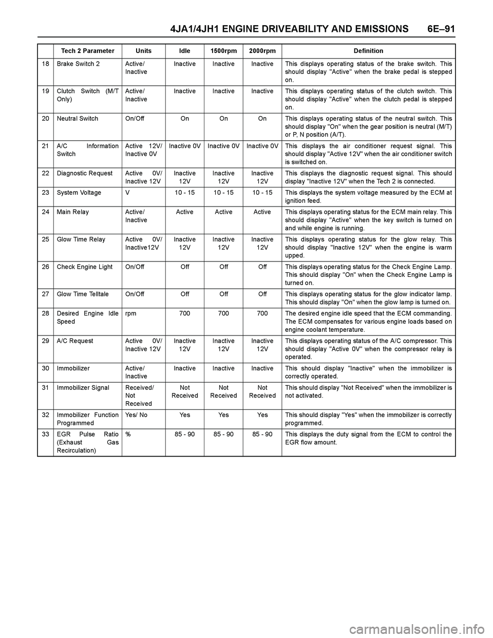
4JA1/4JH1 ENGINE DRIVEABILITY AND EMISSIONS 6E–91
18 Brake Switch 2 Active/
InactiveInactive Inactive Inactive This displays operating status of the brake switch. This
should display "Active" when the brake pedal is stepped
on.
19 Clutch Switch (M/T
On ly )Active/
InactiveInactive Inactive Inactive This displays operating status of the clutch switch. This
should display "Active" when the clutch pedal is stepped
on.
20 Neutra l Switch On/Off On On On This displa ys o pe rating status of the neutra l switch. This
should display "On" when the gear position is neutral (M/T)
or P, N positio n (A/T).
21 A/C Informa tion
SwitchActive 12V/
Inactive 0VInactive 0V Inactive 0V Inactive 0V This displays the air conditioner request signal. This
should display "Active 12V" when the air conditioner switch
is switched on.
22 Dia gnostic Re quest Activ e 0V/
Inactive 12VIna ctiv e
12VInactive
12VIna ctiv e
12VThis displays the diagnostic request signal. This should
display "Inactive 12V" when the Tech 2 is connected.
23 System Voltage V 10 - 15 10 - 15 10 - 15 This displays the system voltage measured by the ECM at
ignition feed.
24 Ma in Re la y Activ e /
InactiveActive Active Active This displays operating status for the ECM main relay. This
should display "Active" when the key switch is turned on
and while engine is running.
25 Glow Time Relay Activ e 0V/
Inactive12VIna ctiv e
12VInactive
12VIna ctiv e
12VThis displays operating status for the glow relay. This
should display "Inactive 12V" when the engine is warm
uppe d.
26 Check Engine Light On/Off Off Off Off This displays operating status for the Check Engine Lamp.
This should display "On" when the Check Engine Lamp is
turned on.
27 Glow Time Telltale On/Off Off Off Off This displays operating status for the glow indicator lamp.
This sho uld display "On" whe n the glo w la mp is turne d o n.
28 Desired Engine Idle
Speedrpm 700 700 700 The desired engine idle speed that the ECM commanding.
The ECM compensates for various engine loads based on
engine coolant temperature.
29 A/C Re que st Activ e 0V/
Inactive 12VIna ctiv e
12VInactive
12VIna ctiv e
12VThis displays operating status of the A/C compressor. This
should display "Active 0V" when the compressor relay is
operated.
30 Immo bilize r Activ e /
InactiveInactive Inactive Inactive This should display "Inactive" when the immobilizer is
correctly operated.
31 Immo bilize r Signal Rece iv ed/
Not
Rece iv edNo t
Receive dNot
Re ceive dNot
Re ce iv e dThis sho uld displa y "No t Receive d" whe n the immo bilize r is
not activated.
32 Immo bilize r Function
ProgrammedYes/ No Yes Yes Yes This should display "Yes" when the immobilizer is correctly
programmed.
33 EGR Pulse Ratio
(Ex ha ust Ga s
Recirculatio n)% 85 - 90 85 - 90 85 - 90 This displays the duty signal from the ECM to control the
EGR flow amount. Tech 2 Parameter Units Idle 1500rpm 2000rpm Definition