Page 746 of 4264
8A-88 ELECTRICAL-BODY AND CHASSIS
REMOVAL AND INSTALLATION
This illustration is based on RHD model
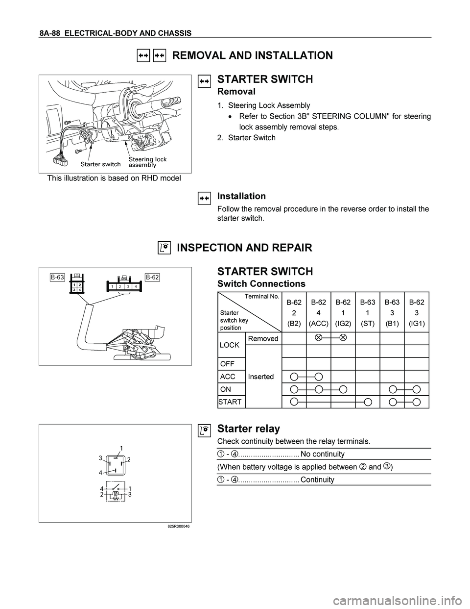
STARTER SWITCH
Removal
1. Steering Lock Assembly
� Refer to Section 3B" STEERING COLUMN" for steering
lock assembly removal steps.
2. Starter Switch
Installation
Follow the removal procedure in the reverse order to install the
starter switch.
INSPECTION AND REPAIR
STARTER SWITCH
Switch Connections
Terminal No.
Starter
switch key
position B-62
2
(B2)B-62
4
(ACC)B-62
1
(IG2) B-63
1
(ST) B-63
3
(B1)B-62
3
(IG1)
Removed
OFF
ACC Inserted
ON
START
LOCK
825R300046
Starter relay
Check continuity between the relay terminals.
1 - 4............................. No continuity
(When battery voltage is applied between 2 and 3)
1 - 4............................. Continuity
Page 936 of 4264

8A-278 ELECTRICAL-BODY AND CHASSIS
Low Fuel Indicator Light Inspection
1. Disconnect the fuel tank unit wire connector.
2. Turn the key switch on. Check that the bulb lights.
If operation is not correct, remove and check the bulb or circuit.
or If check whether low fuel turns on fuel input (B-24) at the
time of open and key on.
� meter is check at low fuel
140R300006
Check level sensor operation
1. Remove the fuel tank unit.
2.
Apply battery voltage between terminal (B) and (C) through
a 1.12 watt bulb. Check that the bulb lights.
Note:
It will take a short time for the bulb light.
3. Submerge the sensor in fuel. Check that the bulb goes out.
If operation is not correct, replace the fuel tank unit.
BRAKE SYSTEM WARNING LIGHT
The brake system warning light comes on while the parking
brake is set and the engine run position.
Note:
The parking brake indicator light circuit is designed to
prevent driving of the vehicle with the parking brake on.
It does not indicate the condition of the parking brake
system.
The parking brake switch is in parallel with the brake fluid
switch.
The brake system warning light also comes on when reservoir
brake fluid level falls below the specified limit with the parking
brake released and the engine run position.
Page 960 of 4264
8A-302 ELECTRICAL-BODY AND CHASSIS
TROUBLESHOOTING
QUICK CHART FOR CHECK POINTS
Check Points
Fuse
C-14
(20A) Power
Window &
Door Lock
Switch Door
Lock
SwitchKey CYLN
Der switch Door Lock Actuator
Cable
Trouble Mode Driver’s
side Driver’s
side D/S P/S Passen
ger’s
side RR-RH RR-LHHarness
1. All the doors do not
lock and unlock
2. All the doors do not
get locked (or
unlocked)
3. Driver’s side door
does not get locked
(or unlocked)
4. FRT passenger’s side
door does not get
locked (or unlocked)
5. RR door-RH does not
get locked (or
unlocked)
6. RR door-LH does not
get locked (or
unlocked)
7. Door lock does not
operate when
operating from the
driver’s seat side
Page 1043 of 4264
ELECTRICAL-BODY AND CHASSIS 8A-385
KEYLESS ENTRY
PARTS LOCATION (RHD)
RTW48AXF024201 & RTW48AXF024301
Page 1049 of 4264
ELECTRICAL-BODY AND CHASSIS 8A-391
Remote key
Remove Key Assembly
Replacing the battery in the remote control unit
Replace the battery as soon as the range of the remote control
starts to become reduced.
Open the underside of the remote control unit by removing the
battery cover with a screwdriver as shown in the illustration.
Replace the battery, ensuring that it is inserted correctly.
Replace the battery cover so that it engages audibly. The
battery change must be performed within 3 minutes, otherwise
the remote control will have to be reprogrammed. Make sure
that you dispose of old batteries in accordance with
environmental protection regulations.
604RW055
Page 1050 of 4264
8A-392 ELECTRICAL-BODY AND CHASSIS
TECH-2 OPERATION AND PROGRAMING
KEYLESS ENTRY
General Description
When the anti-theft and keyless entry control unit and/or the
transmitters (remote keys) are replaced, the security codes
and/or transmitter ID codes must be programmed by using he
Tech-2. The following pages show the procedures to program
in regard to the anti-theft and keyless entry system. Please
refer to Tech-2 scan tool user’s guide in detail.
901RW180
Legend
(1) PCMCIA Card (4) DLC Cable
(2) RS 232 Loop Back Connector (5)Tech–2
(3) SAE 16/19 Adaptor
Page 1051 of 4264

ELECTRICAL-BODY AND CHASSIS 8A-393
060RW009
Tech-2 Features
1. Tech-2 is a 12volt system. Do not apply 24 volts.
2. After connecting and/or installing the vehicle
communication interface (VCI) module, PCMCI
A
card and data link connector (DLC) to the Tech-
2, connect the tool to the vehicle DLC.
3. Make sure the Tech-2 is OFF when removing o
r
installing the PCMCIA card.
4. The Tech-2 has the capability of two snapshot.
5. The PCMCIA card is sensitive to magnetism and
static electricity, so care should be taken in the
handling of the card.
6. The Tech-2 can not plot a graph when replaying
a snapshot.
7.
Always return to the Main Menu by pressing the
EXIT key several times before shutting down.
8. To clear diagnostic trouble codes (DTCs), open
Application Menu and press "Clear DTC ".
060R300015
Getting Started
Before operating the Isuzu PCMCIA card with the
Tech-2, the following steps must be performed:
1. The Isuzu System PCMCIA card inserts into the
Tech-2.
2. Connect the SAE 16/19 adapter to the DLC
cable.
3. Connect the DLC cable to the Tech-2.
4. Mark sure the vehicle ignition is off.
5. Connect the Tech-2 SAE 16/19 adapter to the
vehicle DLC.
Page 1054 of 4264
8A-396 ELECTRICAL-BODY AND CHASSIS
RTW38DLH000101
Menu
The left table shows witch functions are used for the
available equipment versions.
NOTE: Marked items are not applied for keyless entry
system.
DTC
On OBD has three options available in the Tech-2
DTC mode to display the enhanced information
available.
� Read DTC Info Ordered By Priority.
� Read DTC Info As Stored By ECU.
� Clear DTC and Alarm Code Info.
Clear DTC Information
To clear Diagnostic Trouble Codes (DTCs), Use the
diagnostic scan tool “Clear DTC Information” function.
Tech-2 Data Display
The Tech-2 data values represent values that would
be seen on a normally-keyless entry system.
RTW38DSH001601
Actuator Test
Unlock/Lock Test
Check whether opening and closing of a door lock
can be performed by operation of Tech-2.
1. Turn the key “OFF”.
2. Turn the key “ON”.
3. Check the display and test menu.
4. Operate the Tech-2.
 Power
Window &
Door Lock
Switch Door
Lock
SwitchKey CYLN
Der switch Door")

RTW48AXF024201 & RTW48AXF024301")

 a")
