Page 919 of 4264

ELECTRICAL-BODY AND CHASSIS 8A-261
2. Even when the parking brake lever is pulled, the indicator light does not go off
Checkpoint Trouble Cause Countermeasure
Adjust the SW. installation
position or replace the parking
brake SW. Incorrect the parking brake
SW. adjustment or brake SW.
faulty
NG Thermo unit malfunction
Replace the brake fluid level
SW., or vacuum SW., or
repair a short circuit between
the parking brake SW.
connector 1
C-39
(Lever: 1
R-4) and 9 B-23
or the brake fluid level SW.
connector 2
C-37 and 9
B-23, (or the vacuum SW.
connector 1
C-38 and 9
B-23 : 4JH1-TC ONLY)
Check to see if the indicator
light goes off when the parking
brake SW. connector 1
C-39
(Lever: 1
R-4) is
di t d
Brake fluid level SW. or
vacuum SW. faulty or short
circuit
NG OK
Parking brake SW. installation
position and function
3. Oil pressure warning light does not go off while engine is running
Refer to ENGINE Section
Refer to ENGINE Section
NG Thermo unit malfunction
Repair a short circuit between
1
E-1 and 3 B-24
Check to see the warning light
goes off when the oil pressure
SW. connector
1
E-1 is disconnected
Short circuit
Replace the oil pressure unit
(or the oil pressure SW.)
Continuity between the oil
pressure SW. connector
1
E-1 and the body ground
when the engine is operating
Oil pressure unit (or oil
pressure SW) faulty
NG NG OK
OK
Engine oil pressure
Page 932 of 4264
8A-274 ELECTRICAL-BODY AND CHASSIS
Terminal Connector No. B-23
No. C24SE
1
ABS CONT. (BRAKE)
2
�
3
�
4
�
5
�
6
�
7
�
8
�
9
BRAKE
10
CHARGE
11
TURN (RIGHT)
12
�
13
�
14
�
15
�
16
�
17
ILLUMI (-)
18
ILLUMI (+)
Terminal Connector No. B-24
No. C24SE
1
�
2
4LO
3
OIL PRESSURE
4
�
5
4WD
6
CHECK 4WD
7
�
8
�
9
SPEED (+)
10
4P OUTPUT
11
�
12
STARTER
13
TEMP
14
FUEL
15
FRONT FOG
16
�
17
CHECK ENGINE
18
AIR BAG
19
SEAT BELT
20
BEAM (+)
21
TURN (LEFT)
22
BEAM (-)
23
BEAM (+)
24
�
25
�
26
POWER GND
27
SPEED (-)
28
GND UNIT
29
+B
30
IGN
Page 933 of 4264
ELECTRICAL-BODY AND CHASSIS 8A-275
Connector No. B-23
Terminal Connector place SOUTH
AFRICA SAUDI
ARABIA ISRAEL EC UK OTHER
1
ABS CONT. (BRAKE)
2
CHECK TRANS
3
A/T-P
4
A/T-R
5
A/T-2
6
A/T-L
7
� � � � � � �
8
� � � � � � �
9
BRAKE
10
CHARGE
11
TURN (R)
12
A/T-N
13
A/T-D
14
A/T-3
15
DIFF. LOCK � � � � �
16
A/T OIL TEMP � �
17
ILL (-)
18
ILL (+)
RTW48AXF005901
Page 934 of 4264
8A-276 ELECTRICAL-BODY AND CHASSIS
Connector No. B-24
Terminal Connector place SOUTH
AFRICA SAUDI
ARABIA ISRAEL EC UK OTHER
1
SEDIMENTER
2
4LO
3
OIL PRESS
4
4WD
5
CHECK 4WD
6
GLOW
7
POWER DRIVE
8
� � � � � � �
9
SPEED (+)
10
4P OUTPUT
11
TACHO
12
STARTER
13
TEMP
14
FUEL
RR FOG � � � 15
FRONT FOG � � � � � �
16
ABS CONT. (ABS)
17
CHECK ENGINE
18
AIR BAG
SEAT BELT 19
LOW COOLANT � � � � �
CRUISE SET � � � � 20
BEAM (+) � �
�
21
TURN (LEFT)
22
BEAM (-)
BEAM (+) � � � 23
FRONT FOG � �
�
24
3rd START (A/T)
25
� � � � � � �
26
POWER GND
27
SPEED (-)
28
GND UNIT
29
+B
30
IGN
Page 1014 of 4264
8A-356 ELECTRICAL-BODY AND CHASSIS
INSPECTION AND REPAIR
Switch side
B-57
REAR DEFOGGER SWITCH
Rear Defogger Switch Connections
Terminal No.
SW position 9 7 8
ON
OFF
B-7
REAR DEFOGGER RELAY
Check continuity between the relay terminals.
2- 1......................... No continuity
(When battery voltage is applied between
4 and 3)
2- 1......................... Continuity
INSPECTION OF REAR DEFOGGER HEAT
WIRE
� Heat wires are printed on the inner side of glass.
To clean, use a soft cloth and wipe horizontally along the
wires.
� Never use glass cleaner or equivalent.
� When measuring voltage, wind a piece of tin foil around the
tip of the negative probe and press the foil against the wire
with your finger as shown.
(1) Turn the ignition switch on.
(2) Turn the defogger switch on.
(3) Measure the voltage between the three points on the hea
t
wire and the (-) terminal with a voltmeter.
(4) Check that the voltage becomes smaller from
A to B to C.
Page 1078 of 4264
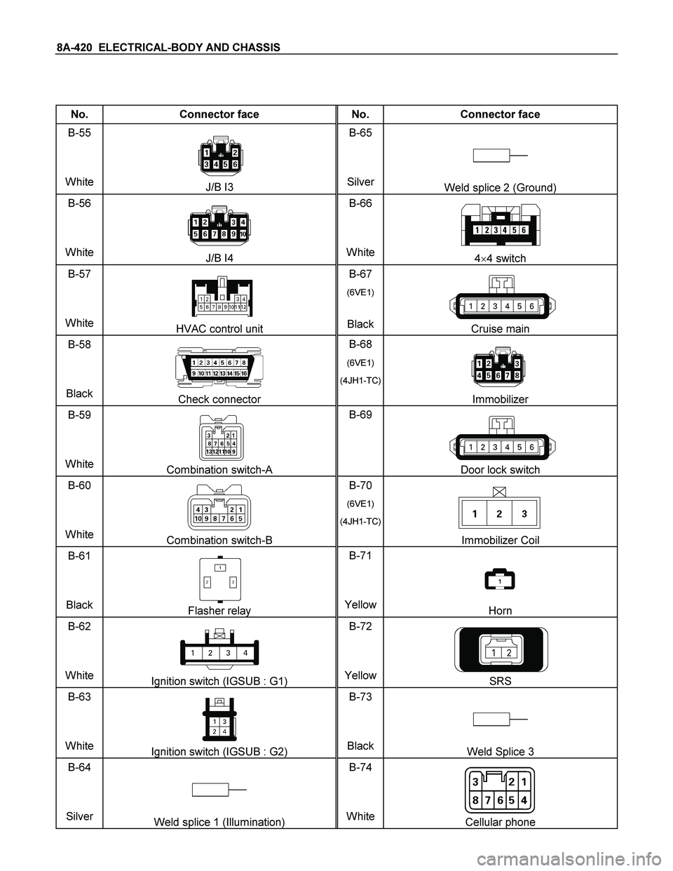
8A-420 ELECTRICAL-BODY AND CHASSIS
No. Connector face No. Connector face
B-55
White
J/B I3 B-65
SilverWeld splice 2 (Ground)
B-56
White
J/B I4 B-66
White4�4 switch
B-57
White
HVAC control unit B-67
(6VE1)
BlackCruise main
B-58
Black
Check connector B-68
(6VE1)
(4JH1-TC)
Immobilizer
B-59
White
Combination switch-A B-69
Door lock switch
B-60
White
Combination switch-B B-70
(6VE1)
(4JH1-TC)
Immobilizer Coil
B-61
Black
Flasher relay B-71
YellowHorn
B-62
White
Ignition switch (IGSUB : G1) B-72
YellowSRS
B-63
White
Ignition switch (IGSUB : G2) B-73
BlackWeld Splice 3
B-64
Silver
Weld splice 1 (Illumination) B-74
WhiteCellular phone
Page 1122 of 4264

6 – 2 TROUBLESHOOTING
Basic Inspection Procedure
Follow the under inspection procedure, when the problem vehicle comes workshop.
Step Inspection point Inspection result YES NO
1 Check the check engine lamp Is the check engine lamp turn
ON ? Go to section
6E “On Board
Diagnostic
(OBD) System
Check" Go to Step 2
2 The battery fluid level and the
gravity Was the problem found? Re-charge the
battery or
replace the
battery Go to Step 3
3 The engine coolant capacity Was the problem found? Replenish the
engine coolant Go to Step 4
4 The engine oil level Was the problem found? Replenish the
engine oil Go to Step 5
5 The air cleaner element Was the problem found? Clean or
replace Go to Step 6
6 The piping fixing condition (oil,
vacuum and fuel piping) Was the problem found? Return normal
condition Go to Step 7
7 The drive belt tension and break Was the problem found? Re-adjust the
tension or
replace Go to Step 8
8 Go to section 6E “On Board
Diagnostic (OBD) System
Check” Was the problem found?
Verify repair Go to Step 9
9 Go to mechanical
troubleshooting chart Was the problem found?
Verify repair —
Page 1136 of 4264

6 – 16 TROUBLESHOOTING
14. Battery Charging and Noise Problem
Visual/physical check the following items before diagnosis.
The drive belt tension.
The battery terminals connection condition.
The ground connection condition.
The generator and the battery fastener condition.
The battery fluid level and specific gravity.
14-1 Battery No Charging
Step Action Value(s) Yes No
1 Was “Visual/Physical Check" performed.
—
Go to Step 2 Go to
visual/physical
check
2 Inspect the brush contact condition on the generator.
Was there poor contact between the brush and the
slip ring? — Repair or
replace the
brush and/or
the slip ring. Go to Step 3
3 Inspect the stator coil on the generator.
Was there an open circuit or the scorching on the
stator coil? —
Replace the
stator coil. Go to Step 4
4 Inspect the rotor coil on the generator.
Was there an open circuit or the scorching on the
rotor coil? —
Replace the
rotor coil. Go to Step 5
5 Inspect the rectifier on the generator.
Was the rectifier defective? — Replace the
rectifier Go to Step 6
6 Inspect the IC regulator.
Was the IC regulator defective? — Replace the IC
regulator. Go to Step 7
7 Are any DTC stored? — Go to indicated
DTC. Solved
14-2 Battery Overcharging
Step Action Value(s) Yes No
1 Was “Visual/Physical Check" performed.
—
Go to Step 2 Go to
visual/physical
check
2 Inspect the terminal circuit.
Were the B and F terminals shorted? — Repair the
short circuit. Go to Step 3
3 Check the regulating voltage.
Was the IC regulator voltage excessive? — Replace the IC
regulator. Go to Step 4
4 Are any DTC stored? — Go to indicated
DTC. Solved


2
CHECK TRANS
3")