Page 4201 of 4264
 7A4-27
Spring specifications
No. Valve nomenclature Free length
(mm / in) Outside
diameter (mm
/ in) Linear
diameter (mm
/ in) Number of
coils
14 Pressure relief 49.")
UNIT REPAIR (JR405E) 7A4-27
Spring specifications
No. Valve nomenclature Free length
(mm / in) Outside
diameter (mm
/ in) Linear
diameter (mm
/ in) Number of
coils
14 Pressure relief 49.0 / 1.929 7.6 / 0.299 1.1 / 0.043 17.3
15 Pressure regulator 30.5 / 1.201 14.0 / 0.551 1.4 / 0.055 5.7
16 Low and reverse brake fail (A) 22.0 / 0.866 7.0 / 0.276 0.6 / 0.024 10.0
17 Fail 23.0 / 0.906 11.0 / 0.433 0.5 / 0.020 13.2
18 Low and reverse brake amp 19.5 / 0.768 7.9 / 0.311 0.5 / 0.020 6.9
19 2 – 4 brake fail (A) 24.8 / 0.976 8.5 / 0.335 0.9 / 0.035 7.8
20 Low clutch amp (B) 26.0 / 1.024 11.0 / 0.433 0.5 / 0.020 6.9
21
Torque converter relief More than 47.2
/ 1.858 9.2 / 0.362 1.6 / 0.063 20.2
22 2 – 4 brake solenoid accumulator 31.4 / 1.236 9.8 / 0.386 1.3 / 0.051 9.3
23 High clutch accumulator 51.0 / 2.008 6.5 / 0.256 0.8 / 0.031 23.5
Oil pressure switch
Apply compressed air (392 kPa/4.0 kg/cm2) to the oil pressure
switch to check the oil pressure switch continuity between the
connector and screw.
244L300011
Oil temperature sensor (harness assembly)
Check the oil temperature sensor resistance between harness
terminals 7 and 6 (ground).
Oil temperature sensor resistance: 2,400�
�� �2,600 ohms
(20�
�� �)
Solenoid
Measure the resistance of each solenoid.
Resistance:
Brown connector – 3.0�
�� �3.4 ohms (20�
�� �C)
Gray connector – 12.0�
�� �13.2 ohms (20�
�� �C)
White connector – 12.2�
�� �13.4 ohms (20�
�� �C)
Reassembly steps
� Coat the parts with ATF before installing them.
� Install the control valve to the control valve lower body.
� Install the oil filter to the control valve lower body.
Page 4209 of 4264
 7A4-35
Return spring � Check the number of effective return spring coils.
If the number is less than the specified minimum, the
return spring must be replaced.
Effective")
UNIT REPAIR (JR405E) 7A4-35
Return spring � Check the number of effective return spring coils.
If the number is less than the specified minimum, the
return spring must be replaced.
Effective return spring coils (standard): 10.2
� Measure the return spring outside diameter, free length,
and linear diameter.
If any of the measured values exceed the specified limit,
the return spring must be replaced.
Return spring measurements (standard):
Outside diameter – 8.0 mm (0.315 in)
Free length – 27.1 mm (1.067 in)
Linear diameter – 1.1 mm (0.043 in)
10R&H40
Reverse clutch piston
� Apply compressed air (392 kPa/4.0 kg/cm
2) to the
reverse clutch piston from the outside to the inside.
The flow of air should be blocked.
11R&H44
�
Apply compressed air (392 kPa/4.0 kg/cm2) to the
reverse clutch piston from inside to the outside.
The flow of air should be unrestricted.
12R&H39
Reassembly steps
Coat the parts with ATF before installing them.
1. Seal ring (high clutch)
Install new seal rings to the high clutch piston.
Page 4212 of 4264

21R&H21
10.Dish plate, drive plates, driven plates, and retaining
plate Install the reverse clutch dish plate (1) the 2 driven plates
(2), the 2 drive plates (3")
7A4-38 UNIT REPAIR (JR405E)
21R&H21
10.Dish plate, drive plates, driven plates, and retaining
plate Install the reverse clutch dish plate (1) the 2 driven plates
(2), the 2 drive plates (3), and retaining plate (4).
248L300003
11.Snap ring
Install the snap ring.
NOTE:
If is careful in the attachment direction of dish plate (1).
22R&H35
�
Install the reverse and high clutch drum to the oil pump
assembly.
� Force compressed air (392 kPa/4.0 kg/cm
2) through the
oil pump oil passages to check high clutch operation.
If the clutch does not operate, the seal ring may be
damaged or the parts may have been installed in the
wrong order.
23CLEAR02
�
Measure the clearance between the high clutch retaining
plate and the snap ring.
If the clearance is outside the specified range, replace
the existing retaining plate with a new plate of the prope
r
size (thickness).
High clutch retaining plate and snap ring clearance
(A): 1.2~1.6 mm (0.047~0.063 in)
Available high clutch retaining plate thicknesses
4.6 mm (0.181 in)
4.8 mm (0.189 in)
Page 4213 of 4264
UNIT REPAIR (JR405E) 7A4-39
248L300004
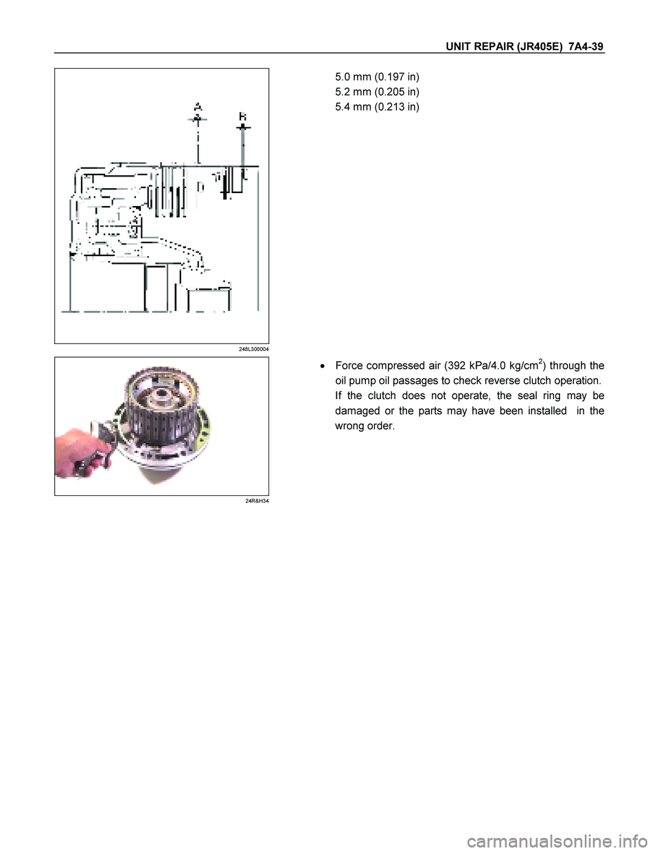
5.0 mm (0.197 in)
5.2 mm (0.205 in)
5.4 mm (0.213 in)
24R&H34
� Force compressed air (392 kPa/4.0 kg/cm2) through the
oil pump oil passages to check reverse clutch operation.
If the clutch does not operate, the seal ring may be
damaged or the parts may have been installed in the
wrong order.
Page 4220 of 4264
7A4-46 UNIT REPAIR (JR405E)
18C&L-SUB28
19.Low one-way clutch
Remove the low one-way clutch.
19C&L-SUB29
20.Snap ring
Remove the snap ring from the low clutch drum.
20C&L-SUB31
21.Bearing
Remove the bearing.
Inspection
Drive plate
� Measure the drive plate facing thickness at 3 points.
� Calculate the average value.
If the average value is less than the specified limit, the
drive plate must be replaced.
Drive plate facing thickness:
Standard – 2.0 mm (0.079 in)
Limit – 1.8 mm (0.071 in)
Return spring
� Check the number of effective return spring coils.
If the number is less than the specified minimum, the
return spring must be replaced.
Effective return spring coils (standard): 9.9
� Measure the return spring outside diameter, free length,
and linear diameter.
If any of the measured values exceed the specified limit,
the return spring must be replaced.
Return spring measurements (standard):
Outside diameter – 9.7 mm (0.382 in)
Page 4224 of 4264

34C&L-SUB15
10.Dish plate, drive plate, driven plate, and retaining plate
Install the low clutch dish plate (1), the 2 mm thick driven
plate (2), the 7 drive pl")
7A4-50 UNIT REPAIR (JR405E)
34C&L-SUB15
10.Dish plate, drive plate, driven plate, and retaining plate
Install the low clutch dish plate (1), the 2 mm thick driven
plate (2), the 7 drive plate (3), the other 6 driven plates (4),
and the retaining plate (5).
NOTE:
Dish plate side with the identification mark must face the
driven plate.
248L300006
11.Snap ring
Install the snap ring to the low clutch drum.
NOTE:
It is careful in the attachment direction of dish plate.
35C&L-SUB38
36CLEAR06
Inspection
� Insert the low one-way clutch inner race to the low clutch
drum.
� Force compressed air (392 kPa/4.0 kg/cm
2) through the
oil passages of the low one-way clutch inner race to
check low clutch operation.
If the low clutch does not operate, the seal rings may be
damaged or the parts may have been installed in the
wrong order.
� Measure the clearance between the low clutch retaining
plate and the snap ring.
If the clearance is outside the specified range, replace
the existing plate with a new plate of the proper size
(thickness).
Low clutch retaining plate and snap ring clearance:
0.9~1.3 mm (0.035~0.051 in)
Available low clutch retaining plate thicknesses
3.8 mm (0.150 in)
4.0 mm (0.157 in)
Page 4231 of 4264
 7A4-57
11CASE-AY01
5. Oil seal
Using a screwdriver, remove the oil seal from the
transmission case.
Inspection
2 – 4 brake drive plate
Measure the 2-")
UNIT REPAIR (JR405E) 7A4-57
11CASE-AY01
5. Oil seal
Using a screwdriver, remove the oil seal from the
transmission case.
Inspection
2 – 4 brake drive plate
Measure the 2-4 brake drive plate facing thickness at 3
points and calculate the average value.
If the average value is less than the specified limit, the 2-4
brake drive plate must be replaced.
2 – 4 brake drive plate facing thickness:
Standard = 2.0 mm (0.079 in)
Limit = 1.8 mm (0.071 in)
Low and reverse brake drive plate
Measure the low and reverse brake drive plate facing
thickness at 3 points and calculate the average value.
If the average value is less than the specified limit, the lo
w
and reverse drive plate must be replaced.
Low and reverse brake drive plate facing thickness:
Standard = 2.0 mm (0.079 in)
Limit = 1.8 mm (0.071 in)
2 – 4 brake return spring
� Check the number of effective 2-4 brake return spring
coils.
Effective return spring coils (Standard): 10.2
� Measure the 2-4 brake return spring outside diameter,
free length, and linear diameter.
If any of the measured values exceed the specified limit,
the 2-4 brake return spring must be replaced.
2 – 4 brake return spring measurements (Standard):
Outside diameter = 6.9 mm (0.272 in)
Free length = 22.5 mm (0.886 in)
Linear diameter = 1.1 mm (0.043 in)
Low and reverse brake return spring
� Check the number of effective low and reverse brake
return spring coils.
Effective return spring coils (standard): 4.8
� Measure the low and reverse brake return spring outside
diameter, free length, and linear diameter.
If any of the measured values exceed the specified limit,
the low and reverse return spring must be replaced.
Low and reverse brake return spring measurements
(Standard):
Outside diameter = 11.2 mm (0.441 in)
Page 4236 of 4264
7A4-62 UNIT REPAIR (JR405E)
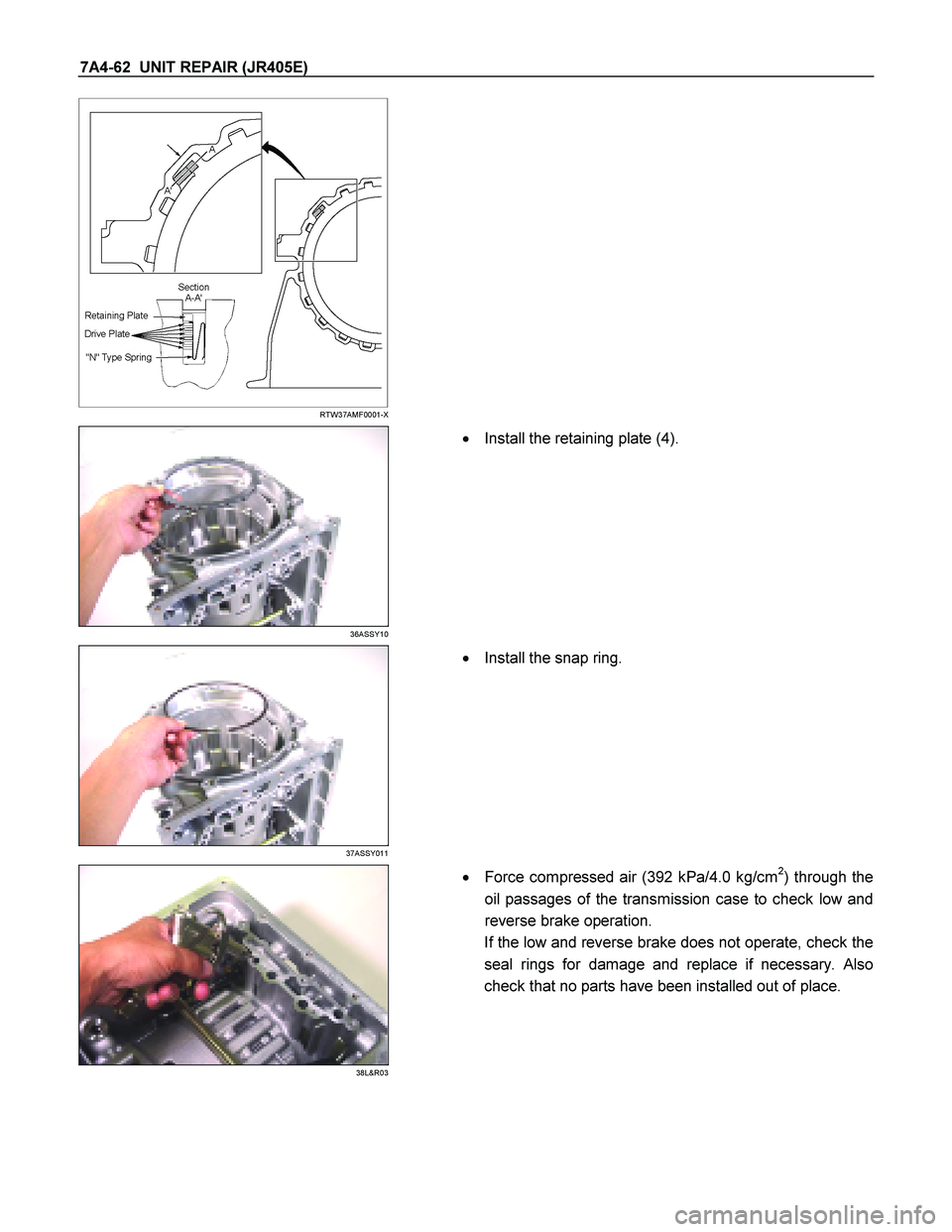
RTW37AMF0001-X
36ASSY10
�
Install the retaining plate (4).
37ASSY011
�
Install the snap ring.
38L&R03
�
Force compressed air (392 kPa/4.0 kg/cm2) through the
oil passages of the transmission case to check low and
reverse brake operation.
If the low and reverse brake does not operate, check the
seal rings for damage and replace if necessary. Also
check that no parts have been installed out of place.

18C&L-SUB28
19.Low one-way clutch
Remove the low one-way clutch.
19C&L-SUB29
20.Snap ring
Remove the snap ring from the low clutch drum.
20C&L-S")