Page 212 of 4264
4B-48 REAR AXLE
5) Constant Noise
Checkpoint Trouble Cause Countermeasure
Replace the rear axle shaftBent rear axle shaft NG
Replace the side bearing
Replace the drive pinion
bearing
Replace the drive pinion and
the ring gear as a set
Replace the drive pinion and
the ring gear as a set
Flat spot on the side bearing
oil seal
BearingFlat spot on the drive pinion
Flat spot on the gear teeth
pilot bearing wear
Drive pinionFlat spot on the drive pinion
gear teeth
Ring gear
Replace the drive pinion and
the ring gear as a setWorn pinion splines oil seal
NG NG NG NG NG
OK OK
OK
Rear axle shaft
Page 214 of 4264
4B-50 REAR AXLE
3. OIL LEAKAGE
1) Differential Carrier Leakage
Checkpoint Trouble Cause Countermeasure
Correct the oil levelToo much gear oil NG
Reapply the liquid gasket
and/or tighten the lock nut to
the specified torque
Reapply the liquid gasket
Tighten the bolts to the
specified torque
Replace the oil seal
Ring gear thrust boltLoose lock nut and/or liquid
Liquid gasket seal bed
Loose bolts
Oil sealWorn or defective oil seal
Differential carrier
Clean the air breatherAir breatherClogged air breather
NG NG NG NG NG
OK OK OK
OK
Gear oil level
Page 215 of 4264
REAR AXLE 4B-51
2) Axle Case Leakage
Checkpoint Trouble Cause Countermeasure
Tighten the drain plug and/or
replace the gasket(s)Loose drain plug and/or
defective gasket(s) NG
Reapply the liquid gasket
Tighten the bolts to the
specified torque
Clean the air breather
Liquid gasket seal bad
Loose bolts
Air breatherClogged air breather
Differential carrier
Replace the axle caseAxle caseCracked axle case
NG NG NG NG
OK OK
OK
Oil filler and drain plug
Page 216 of 4264
4B-52 REAR AXLE
3) Axle Case to Inside Brake Drum Leakage
Checkpoint Trouble Cause Countermeasure
Replace the oil sealWorn or defective oil seal NGOil seal
Page 240 of 4264
4C1-20 FRONT WHEEL DRIVE
6. Using snap ring pliers, remove the snap ring (1) fastening
the ball retainer to the center shaft.
7. Remove ball retainer, ball guide and bellows.
8. Use a hammer and chisel to remove the 3 pawls (above
the large and small boot bands on the UJ side).
CAUTION :
Take care not to damage the bellows during band removal.
9. Remove band (1).
10. Remove bellows.
11. Remove dust seal from UJ.
12. Remove UJ shaft assembly.
13. Remove the mounting bracket fixing bolts, and then
remove DOJ case assembly from the axle case.
14. Remove snap ring and bearing.
15. Remove snap ring and oil seal.
16. Remove bracket.
Inspection And Repair
Make necessary correction or parts replacement if wear,
damage, corrosion or any other abnormal condition are found
through inspection.
Check the following parts.
1. Drive shaft joint assembly
2. DOJ case, ball, ball guide, ball retainer
3. Bellows
4. Bearing
5. Dust seal, oil seal
Page 249 of 4264

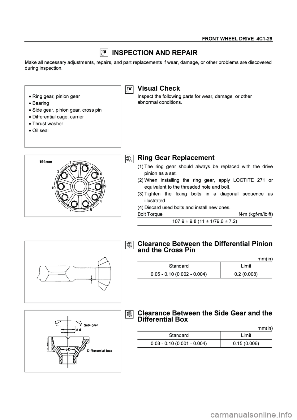
FRONT WHEEL DRIVE 4C1-29
INSPECTION AND REPAIR
Make all necessary adjustments, repairs, and part replacements if wear, damage, or other problems are discovered
during inspection.
� Ring gear, pinion gear
� Bearing
�
Side gear, pinion gear, cross pin
�
Differential cage, carrier
�
Thrust washer
�
Oil seal
Visual Check
Inspect the following parts for wear, damage, or other
abnormal conditions.
Ring Gear Replacement
(1) The ring gear should always be replaced with the drive
pinion as a set.
(2) When installing the ring gear, apply LOCTITE 271 o
r
equivalent to the threaded hole and bolt.
(3) Tighten the fixing bolts in a diagonal sequence as
illustrated.
(4) Discard used bolts and install new ones.
Bolt Torque N�m (kgf�m/lb�ft)
107.9 � 9.8 (11 � 1/79.6 � 7.2)
Clearance Between the Differential Pinion
and the Cross Pin
mm(in)
Standard Limit
0.05 - 0.10 (0.002 - 0.004) 0.2 (0.008)
Clearance Between the Side Gear and the
Differential Box
mm(in)
Standard Limit
0.03 - 0.10 (0.001 - 0.004) 0.15 (0.006)
Page 265 of 4264
FRONT WHEEL DRIVE 4C1-45
INSPECTION AND REPAIR
Make necessary correction or parts replacement if wear, damage or any other abnormal conditions are found
through inspection.
For inspection and servicing of disc caliper, and relative parts, and ABS parts, refer to section 5 Brakes.
� Hub
� Hub bearing
� Bearing outer race
�
Disc
�
Oil seal
�
Knuckle spindle
�
ABS sensor rotor
�
Caliper
Visual Check
Check the following parts for wear, damage or other abnormal
conditions.
Page 268 of 4264

4C1-48 FRONT WHEEL DRIVE
(2) Install the outer and inner bearing into the hub with fingers.
(3) Install oil seal using special tools.
Discard the used oil seal and install a new one.
Installer : 5-8522-0051-0
(J-33161)
Grip : 5-8840-0007-0
(J-8092)
Hub cap Hub
6. Hub and Disc Assembly
12. Hub Cap
Apply grease in the hub and hub cap.
Description Amount g(oz)
Hub 50 (1.76)
Hub cap 20 (0.70)
Outer bearing 6.5 (0.23)
Inner bearing 12 (0.42)
9. Hub nut
Adjustment of front wheel hub bearing preload
1. Tighten spindle nut to 3.0 kg�m (21.7 lb.ft/29.4 N�m) torque.
2. Turn the hub 2-3 turns and loosen the nut just enough so
that it can be turned with the fingers.
3. Turn the nut all the way in with the fingers and check to be
sure the hub has no free play.
4. Measure the bearing preload by pulling one of the wheel
hub studs with a spring scale.
5. Tighten the spindle nut until specified bearing preload Is
obtained.
6. Install the split pin in the nut retainer.
Discard the used split pin and install a new one.
After reassembling, install the disc brake caliper assembly.
Bearing Preload N�
m (kgf�
m/lb�
ft)
New bearing and New oil seal 8-12 (0.8-1.2 / 69-104)
Reuse bearing and New oil seal 8-12 (0.8-1.2 / 69-104)