Page 122 of 4264

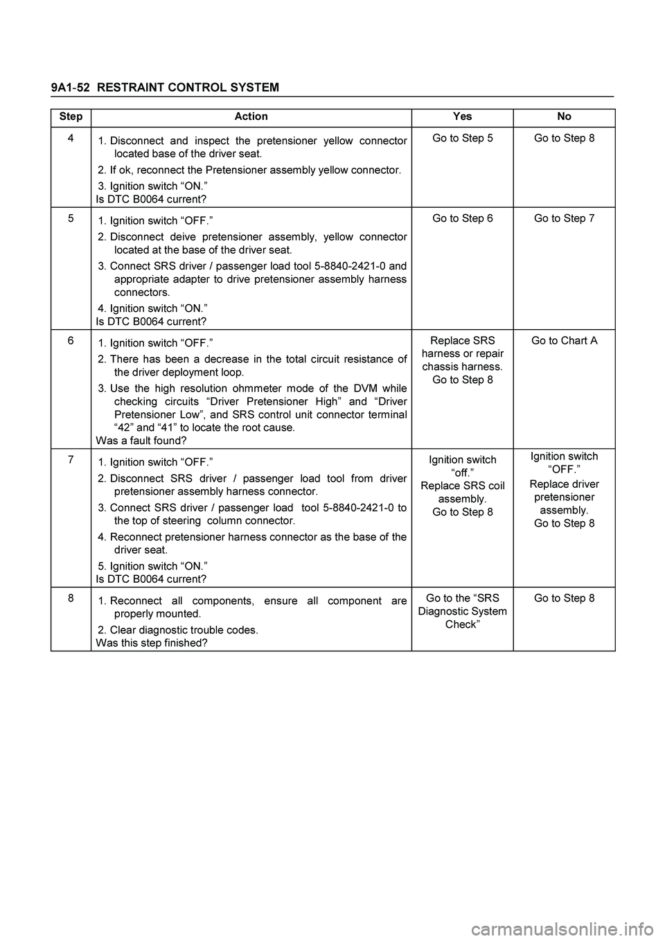
9A1-52 RESTRAINT CONTROL SYSTEM
Step Action Yes No
4
1. Disconnect and inspect the pretensioner yellow connector
located base of the driver seat.
2. If ok, reconnect the Pretensioner assembly yellow connector.
3. Ignition switch “ON.”
Is DTC B0064 current? Go to Step 5 Go to Step 8
5
1. Ignition switch “OFF.”
2. Disconnect deive pretensioner assembly, yellow connector
located at the base of the driver seat.
3. Connect SRS driver / passenger load tool 5-8840-2421-0 and
appropriate adapter to drive pretensioner assembly harness
connectors.
4. Ignition switch “ON.”
Is DTC B0064 current? Go to Step 6 Go to Step 7
6
1. Ignition switch “OFF.”
2. There has been a decrease in the total circuit resistance of
the driver deployment loop.
3. Use the high resolution ohmmeter mode of the DVM while
checking circuits “Driver Pretensioner High” and “Driver
Pretensioner Low”, and SRS control unit connector terminal
“42” and “41” to locate the root cause.
Was a fault found? Replace SRS
harness or repair
chassis harness.
Go to Step 8 Go to Chart A
7
1. Ignition switch “OFF.”
2. Disconnect SRS driver / passenger load tool from driver
pretensioner assembly harness connector.
3. Connect SRS driver / passenger load tool 5-8840-2421-0 to
the top of steering column connector.
4. Reconnect pretensioner harness connector as the base of the
driver seat.
5. Ignition switch “ON.”
Is DTC B0064 current? Ignition switch
“off.”
Replace SRS coil
assembly.
Go to Step 8 Ignition switch
“OFF.”
Replace driver
pretensioner
assembly.
Go to Step 8
8
1. Reconnect all components, ensure all component are
properly mounted.
2. Clear diagnostic trouble codes.
Was this step finished? Go to the “SRS
Diagnostic System
Check” Go to Step 8
Page 124 of 4264

9A1-54 RESTRAINT CONTROL SYSTEM
DTC Will Clear When
The ignition switch is turned “OFF”.
DTC Will Set When
The combined resistance of the driver pretensioner
assembly, harness wiring circuits “Driver Pretensioner
High” and “Driver Pretensioner Low”, and connector
terminal contact is above a specified value. This test
run once each ignition cycle during the “Resistance
Measurement Test” when:
1.
No “higher priority faults” are detected during “Turn–
ON”
2.
“Ignition 1” voltage is in the specified value.
Action Taken
SRS control unit turns “ON” the “AIR BAG” warning
lamp and sets DTC B0065.
DTC Chart Test Description
Number(s) below refer to step number(s) on the
diagnostic chart:
2.
This test determines whether the malfunction is in
the SRS control unit.
3.
This test verifies proper connection of the yellow
connector at the base of the driver seat.
4.
This test checks for proper contact and/or corrosion
of the connector terminals at the base of the drive
r
seat.
5.
This test isolate the malfunction to one side of the
SRS coil assembly yellow connector located at the
base of the driver seat.
6.
This test determines whether the malfunction is due
to high resistance in the wiring.
7.
This test determines whether the malfunction is in
the driver pretensioner assembly.
Diagnostic Aids
An intermittent condition is likely to be caused by a poor
connection at the drive pretensioner harness connecto
r
terminals “1” and “2”, SRS control unit terminals “42”
and “41”, or a poor wire to terminal connection in circuit
“Driver Pretensioner High” or “Driver Pretensioner Low”
The test for this diagnostic trouble code is only run while
the “AIR BAG” warning lamp is performing the bulb
check. When a scan tool “Clear Codes” command is
issued and the malfunction is still present, the DTC will
not reappear until the next ignition cycle.
DTC B0065 (Flash Code 65) Driver Pretensioner Squib Circuit High Resistance
Step Action Yes No
1 Perform the “SRS Diagnostic System Check”.
Was the “SRS Diagnostic System Check” performed? Go to Step 2 Repeat the “SRS
Diagnostic System
Check”
2
1. Check the driver pretensioner squib circuit for open.
2. If the problem found repair as necessary.
Was a problem found? Verify repair Go to Step 3
3
1. Ignition switch “OFF.”
2. Disconnect SRS coil assembly yellow connector located at
base of the driver seat.
Is the connector connected properly? Go to Step 4 Seat pretensioner
assembly
connector
properly.
Go to Step 8
Page 146 of 4264

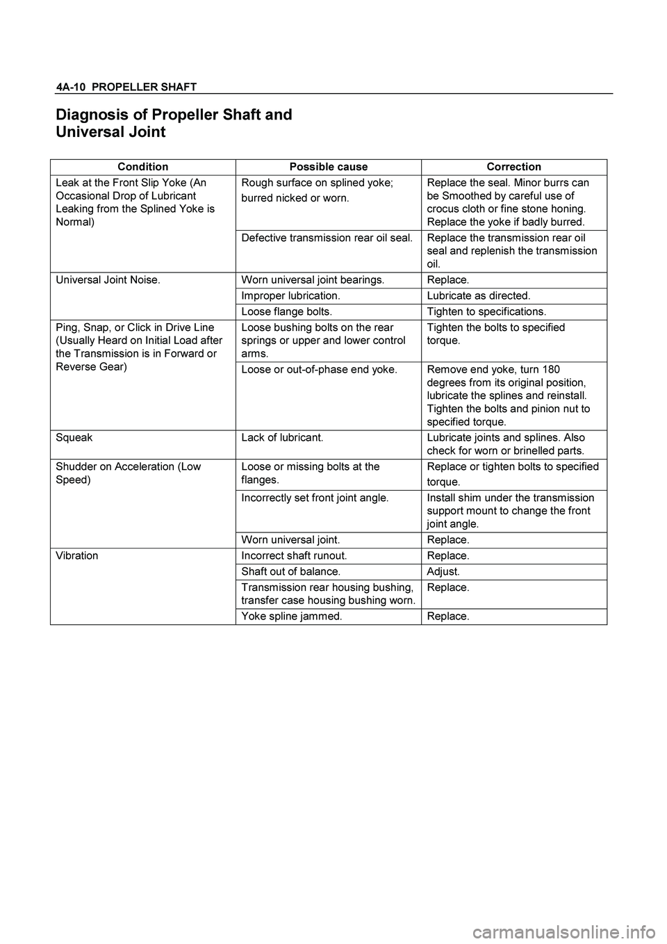
4A-10 PROPELLER SHAFT
Diagnosis of Propeller Shaft and
Universal Joint
Condition Possible cause Correction
Rough surface on splined yoke;
burred nicked or worn. Replace the seal. Minor burrs can
be Smoothed by careful use of
crocus cloth or fine stone honing.
Replace the yoke if badly burred. Leak at the Front Slip Yoke (An
Occasional Drop of Lubricant
Leaking from the Splined Yoke is
Normal)
Defective transmission rear oil seal. Replace the transmission rear oil
seal and replenish the transmission
oil.
Worn universal joint bearings. Replace.
Improper lubrication. Lubricate as directed.
Universal Joint Noise.
Loose flange bolts. Tighten to specifications.
Loose bushing bolts on the rear
springs or upper and lower control
arms. Tighten the bolts to specified
torque. Ping, Snap, or Click in Drive Line
(Usually Heard on Initial Load after
the Transmission is in Forward or
Reverse Gear)
Loose or out-of-phase end yoke. Remove end yoke, turn 180
degrees from its original position,
lubricate the splines and reinstall.
Tighten the bolts and pinion nut to
specified torque.
Squeak Lack of lubricant. Lubricate joints and splines. Also
check for worn or brinelled parts.
Loose or missing bolts at the
flanges. Replace or tighten bolts to specified
torque.
Incorrectly set front joint angle. Install shim under the transmission
support mount to change the front
joint angle.
Shudder on Acceleration (Low
Speed)
Worn universal joint. Replace.
Incorrect shaft runout. Replace.
Shaft out of balance. Adjust.
Transmission rear housing bushing,
transfer case housing bushing worn.Replace.
Vibration
Yoke spline jammed. Replace.
Page 197 of 4264
REAR AXLE 4B-33
Disassembly
1. Remove bolt.
2. Remove ring gear.
3. Drive out lock pin using a long drift Punch.
425RS042
4. Check the amount of backlash between pinion
gear on side gear before removal of cross pin.
Backlash :
0.13-0.18 mm (0.005–0.007 in)
5. Remove the cross pin by using a brass drift
punch and hammer.
425RS043
6. Take out pinion gear, side gear and thrust
washer.
Inspection and Repair
Make necessary correction or parts replacement if
wear, damage, corrosion or any other abnormal
conditions are found through inspection.
Check the following parts:
�
Ring gear, pinion gear
�
Bearing
�
Side gear, pinion gear, cross pin
�
Differential cage, carrier
�
Thrust washer
�
Oil seal
Clearance between pinion gear and cross pin:
mm(in)
Standard Limit
0.06 - 0.12
(0.002 - 0.005) 0.2 (0.008)
425L100012
Clearance between side gear and differential cage.
mm(in)
Standard Limit
0.05 - 0.11
(0.002 - 0.004) 0.15 (0.006)
Page 198 of 4264
4B-34 REAR AXLE
425R300010
Play in splines between the side gear and axle shafts.
mm(in)
Standard Limit
0.08 - 0.38
(0.003 - 0.015) 0.5 (0.02)
425L100014
Differential cage
Check the ring gear the side gear fitting faces and the
cross pin hole for scores or roughness. Correct as
necessary. Slight scores or roughness may be
corrected with an oil stone or fine sand paper.
425R300006
Ring gear replacement:
1. The ring gear should always be replaced with the
drive pinion as a set.
2. Discard use bolts and install new ones.
3.
Apply LOCTITE 271 on bolt from the end of thread
to the middle of straight portion.
4. Tighten the fixing bolts in a diagonal sequence as
illustrated.
Torque : 108 N�m (11 kg�m/80 lb�ft)
425RW033
Page 202 of 4264

4B-38 REAR AXLE
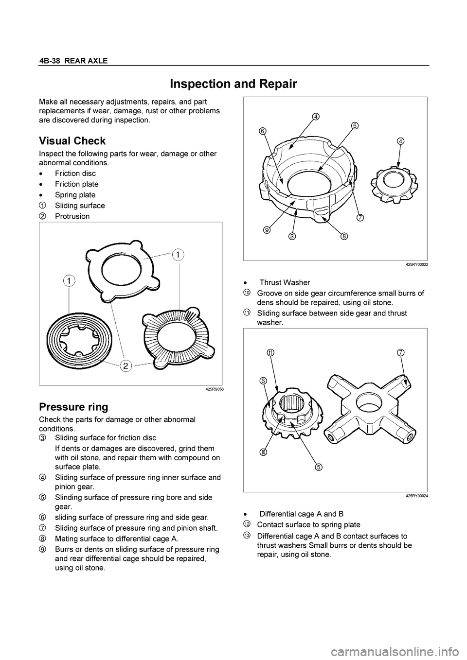
Inspection and Repair
Make all necessary adjustments, repairs, and part
replacements if wear, damage, rust or other problems
are discovered during inspection.
Visual Check
Inspect the following parts for wear, damage or other
abnormal conditions.
�
Friction disc
�
Friction plate
�
Spring plate
1 Sliding surface
2 Protrusion
425RS056
Pressure ring
Check the parts for damage or other abnormal
conditions.
3 Sliding surface for friction disc
If dents or damages are discovered, grind them
with oil stone, and repair them with compound on
surface plate.
4 Sliding surface of pressure ring inner surface and
pinion gear.
5 Slinding surface of pressure ring bore and side
gear.
6 sliding surface of pressure ring and side gear.
7 Sliding surface of pressure ring and pinion shaft.
8 Mating surface to differential cage A.
9 Burrs or dents on sliding surface of pressure ring
and rear differential cage should be repaired,
using oil stone.
425RY00022
�
Thrust Washer
10 Groove on side gear circumference small burrs of
dens should be repaired, using oil stone.
11 Sliding surface between side gear and thrust
washer.
425RY00024
�
Differential cage A and B
12 Contact surface to spring plate
13 Differential cage A and B contact surfaces to
thrust washers Small burrs or dents should be
repair, using oil stone.
Page 207 of 4264
REAR AXLE 4B-43
TROUBLESHOOTING
Refer to this Section to quickly diagnose and repair
rear axle problems.
Each troubleshooting chart has three headings
arranged from left to right.
(1) Checkpoint
(2) Trouble Cause
(3) Countermeasure
This Section is divided into five sub-sections:
1. Abnormal Rear Axle Noise
1) Noise when the engine is driving the vehicle
2) Noise when the vehicle is coasting
3) Intermittent noise
4) Noise when the vehicle is turning
5) Constant noise
2. Vibration
3. Oil Leakage
1) Differential carrier leakage
2) Axle case leakage
3) Axle case to inside hub leakage
4) Axle case to inside brake drum leakage
4. Power Not Being Transmitted to the Wheels
(Propeller Shaft Operation is Normal)
Page 208 of 4264
4B-44 REAR AXLE
1. ABNORMAL REAR AXLE NOISE
1) Noise when the Engine is Driving the Vehicle
Checkpoint Trouble Cause Countermeasure
Replenish the gear oilInsufficient gear oil NG
Differential side bearingAdjust the differential side
bearing preload
Replace the drive pinion
bearings
Adjust the drive pinion bearing
preload
Replace the gear oil
Loose differential side
bearings
Worn drive pinion bearings
Loose drive pinion bearings
Wrong or poor grade gear oil
Drive pinion to ring gear
backlash
Drive pinion end play
Adjust the backlashToo much or too little backlash
Continued on the next pageOK OK
NG NG NG NG NG
OK
OK
Rear axle gear oil
Replace the differential side
bearingsWorn differential side bearings NG