Page 247 of 4264
FRONT WHEEL DRIVE 4C1-27
MINOR COMPONENTS
Disassembly Steps
1. Bolt
2. Ring gear
�
3. Lock pin
�
4. Cross pin
5. Pinion gear
6. Side gear
7. Thrust washer
8. Differential cage
Page 248 of 4264
4C1-28 FRONT WHEEL DRIVE
Important Operations
3. Lock Pin
Break staking on the lock pin using a 5 mm (0.20 in.) diameter
drill.
4. Cross Pin
Remove the cross pin using a soft metal rod and a hammer.
Page 251 of 4264
FRONT WHEEL DRIVE 4C1-31
REASSEMBLY
MINOR COMPONENTS
Reassembly Steps
1. Differential cage
2. Thrust washer
3. Side gear
�
4. Pinion gear
�
5. Cross pin
�
6. Lock pin
�
7. Ring gear
�
8. Bolt
Important Operations
4. Pinion Gear
Install the pinion gear by engaging it with the side gears while
turning both pinion gears simultaneously in the same direction.
Page 252 of 4264
4C1-32 FRONT WHEEL DRIVE
5. Cross Pin
(1) Be sure to install the cross pin so that it is in alignment with
the lock pin hole in the differential cage.
(2)
Adjust the backlash between the side gear and the pinion
gear.
mm(in)
Backlash 0.10 - 0.20 (0.004 - 0.008)
Thickness of thrust washers available
mm(in)
1.00, 1.05, 1.10 (0.039, 0.041, 0.043)
6. Lock Pin
After lock pin installation, stake the cage to prevent discharge
of the lock pin.
7. Ring Gear
When installing the ring gear, apply LOCTITE 271 or
equivalent to the threaded hole and bolt.
8. Bolt
Tighten the bolts in diagonal sequence as illustrated.
Bolt Torque N�m (kgf�m/lb�ft)
107.9 � 9.8 (11 � 1/79.6 � 7.2)
Note :
Discard used bolts and install new ones.
Note that all bolts have a left hand thread.
Page 255 of 4264

New bearing 2.26 (23/20)
Used bearing0.98 - 1.18
(10 - 12/8.7 - 10.4)
(2) Clean the side bearin")
FRONT WHEEL DRIVE 4C1-35
Tighten the nut to the specified torque.
N�m (kgf�m/lb�ft)
New bearing 2.26 (23/20)
Used bearing0.98 - 1.18
(10 - 12/8.7 - 10.4)
(2) Clean the side bearing bores. Install the dial indicator with
the discs and Arbor. Install and tighten the bearing caps to
the specified torque.
Torque N�
m (kgf�
m/lb�
ft)
98.1 � 9.8 (10.0 � 1.0/72.3 � 7.2)
1 Dial indicator : 5-8840-0126-0
(J-8001)
2 Disc (2 pcs.) : 5-8840-2088-0
(J-23597-8)
3 Arbor : 5-8840-0128-0
(J-23597-1)
4 Gage plate : 5-8840-2087-0
(J-23597-7)
(3) Set the dial indicator to “0”. Place it on the mounting post of
the gaging arbor with the contact button touching the
indicator pad. Force the dial indicator downward until the
needle has made a half turn clockwise. Tighten down the
dial indicator in this position.
(4) Position the plunger on the gage plate. Move the gaging
arbor slowly back and forth and locate the position at which
the dial indicator shows the greatest deflection. At this
point, once again set the dial indicator to “0”.
Repeat the procedure to verify the “0” setting.
Page 262 of 4264
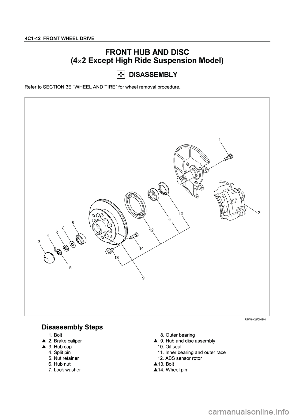
4C1-42 FRONT WHEEL DRIVE
FRONT HUB AND DISC
(4�
�� �2 Except High Ride Suspension Model)
DISASSEMBLY
Refer to SECTION 3E “WHEEL AND TIRE” for wheel removal procedure.
RTW34CLF000801
Disassembly Steps
1. Bolt
�
2. Brake caliper
�
3. Hub cap
4. Split pin
5. Nut retainer
6. Hub nut
7. Lock washer
8. Outer bearing
�
9. Hub and disc assembly
10. Oil seal
11. Inner bearing and outer race
12. ABS sensor rotor
�
13. Bolt
�
14. Wheel pin
Page 266 of 4264
4C1-46 FRONT WHEEL DRIVE
REASSEMBLY
Refer to SECTION 3E “WHEEL AND TIRE” for wheel removal procedure.
RTW34CLF000901
Reassembly Steps
�
1. Wheel pin
�
2. Bolt
�
3. ABS sensor rotor
�
4. Inner bearing and outer race
�
5. Oil seal
�
6. Hub and disc assembly
7. Outer bearing
8. Lock washer
�
9. Hub nut
10. Nut retainer
11. Split pin
�
12. Hub cap
13. Brake caliper
�
14. Bolt
Page 267 of 4264
FRONT WHEEL DRIVE 4C1-47
Important Operations
1. Wheel Pin
(1) Place hub on a wood workbench or a block of wood,
approx. 6” by 6” to protect the wheel stud ends and threads.
(2) Install wheel stud using a hammer.
Be sure wheel stud is started squarely and seats
completely.
(3) Align index marks and install hub to disc.
2. Bolt
Torque N�
m (kgf�
m/lb�
ft)
103 �
10 (10.5 �
1/75.9 �
7.2)
3. ABS sensor rotor
(1) Set a new ABS sensor rotor, if replacement is required.
(2) Install the ABS sensor rotor in the hub, using special tools.
Installer : 5-8840-2789-0
Grip : 5-8840-0007-0
Refer to the section Brake.
4. Inner Bearing and Outer Race
5. Oil Seal
�
Outer Bearing Outer Race
(1) Install the bearing outer race by driving into the hub.
Installer (Outer) : 5-8822-0053-0 (J-29016)
Installer (Inner) : 5-8822-0054-0 (J-29015)
Drive handle : 5-8840-0007-0 (J-8092)

 diameter
drill.
4. Cross Pin
Remove the cross pin using a soft metal rod")

 Be sure to install the cross pin so that it is in alignment with
the lock pin hole in the differential cage.
(2)
Adjust the backlash between")

 Place hub on a wood workbench or a block of wood,
approx. 6” by 6” to protect the wheel stud ends and threads.
(2) Install whee")