Page 344 of 4264

5A-28 BRAKE CONTROL SYSTEM
Isolation Valve Test
Purpose: The purpose of this test is to detect brake
pipe and valve line harness wire for wrong connections
and valve trouble.
This test will help you confirm the result of your repair
service including the removal/reinstallation of brake
pipe, valve line harness and valve.
Test conditions: The ignition key is in the “ON” position
with the four wheels lifted up. The brake pedal is
stepped on, released and stepped on again with the
parking brake released.
Test procedure:
1. Connect Tech 2 with the vehicle, and select
Actuaor Test from the menus.
2. Select a Solenoid Valve Test Menu from the
Actuaor Test Menus.
060L300002
3. Select Isolation Valve from the Valve Select Menus.
4. Step on the brake pedal.
5. Release the brake pedal.
6. Make sure that the Isolation Valve “ON” aimed at by
Tech 2 and the wheel locked position are the same.
If different, check brake pipe, valve line harness
wiring and H/UNIT. Repair is needed if abnormality
is found.
7. Conduct Step 2 through Step 5 above on all the
four wheels.
060L300002
CAUTION: When conducting this test, please
observe the following cautions.
1. Do not start the engine.
2. Lift up the vehicle at a level floor.
�
�� � Secure a clearance from the floor surface
enough to allow the lifted tire to rotate.
3. Maintain the lift up.
4. Wipe the floor surface to remove water and oil
so that the surface may become unslippery.
5. Do not load the vehicle.
�
�� � When lifting up the vehicle, be sure to
observe the lifting up points. Refer to
vehicle lifting points in 0A section.
Page 355 of 4264

BRAKE CONTROL SYSTEM 5A-39
Symptom Diagnosis
The symptoms that cannot be indicated by warning
lamp can be divided in the following five categories:
1. ABS works frequently but vehicle does not
decelerate.
2. Uneven braking occurs while ABS works.
3. The wheels are locked.
4. Brake pedal feel is abnormal.
5. Braking sound (from EHCU) is heard while not
braking.
6. No ABS warning lamp
These are all attributable to problems which cannot be
detected by EHCU self-diagnosis. Use the customer
complaint and a test to determine which symptom is
present.
ABS Works Frequently But Vehicle Does Not Decelerate
Step Action
Value(s) Yes No
1 Is braking force distribution normal between front
and rear of vehicle?
- Go to Step 2 Repair brake
parts.
Go to Step 7
2 Are axle parts installed normally?
- Go to Step 3 Repair axle
parts.
Go to Step 7
3 Is there play in each or any wheel speed sensor?
- Repair wheel
speed sensor.
Go to Step 7 Go to Step 4
4 Is there damage, or powered iron sticking to each or
any wheel speed sensor/sensor rotor?
- Replace
wheel speed
sensor or
sensor rotor.
Go to Step 8 Go to Step 5
5 Is the each wheel speed sensor output normal?
- Go to Step 6 Replace
wheel speed
sensor or
repair
harness.
Go to Step 7
6 Is the 4WD control system function normal?
- 2-4WD Repair
or Go to Step
7 Repair or
replace 2-
4WD control
System.
Go to Step 7
7 Reconnect all components, ensure all components
are properly mounted.
Was this step finished?
- Repeat the
“Basic
diagnostic
flow chart” Go to Step 7
Page 356 of 4264

5A-40 BRAKE CONTROL SYSTEM
Uneven Braking Occurs While ABS Works
Step Action
Value(s) Yes No
1 Is there play in each or any sensor?
- Repair.
Go to Step 5 Go to Step 2
2 Damage or powdered iron sticking to each or any
sensor/sensor rotor?
- Repair.
Go to Step 5 Go to Step 3
3 Is the each sensor output normal?
- Go to Step 4 Replace
sensor or
repair
harness.
Go to Step 5
4 Is brake pipe connecting order correct?
Note: Check the EHCU type for specification, when
the EHCU is replaced.
(Specification; 2WD Model or 4WD Model) - Replace
EHCU.
Go to Step 5 Reconnect
brake pipe
correctly.
Go to Step 5
5 Reconnect all components, ensure all components
are properly mounted.
Was this step finished?
- Repeat the
“Basic
diagnostic
flow chart” Go to Step 5
The Wheels Are Locked
Step Action Value(s) Yes No
1 Is ABS working?
- Go to Step 2 Go to Step 4
2 Is vehicle speed under 5 km/h?
- Go to Step 3 Normal.
3 Is the each sensor output normal?
- Go to Step 4 Replace
sensor or
repair
harness.
Go to Step 6
4 Is 2-4WD system function normal?
- Go to Step 5 Replace 2-
4WD controll
unit or repair
harness.
Go to Step 6
5 Is EHCU grounded properly?
Note: Check the EHCU type for specification, when
the EHCU is replaced.
(Specification; 2WD Model or 4WD Model) - Replace
EHCU.
Go to Step 6 Repair.
Go to Step 6
6 Reconnect all components, ensure all components
are properly mounted.
Was this step finished?
- Repeat the
“Basic
diagnostic
flow chart” Go to Step 6
Page 407 of 4264

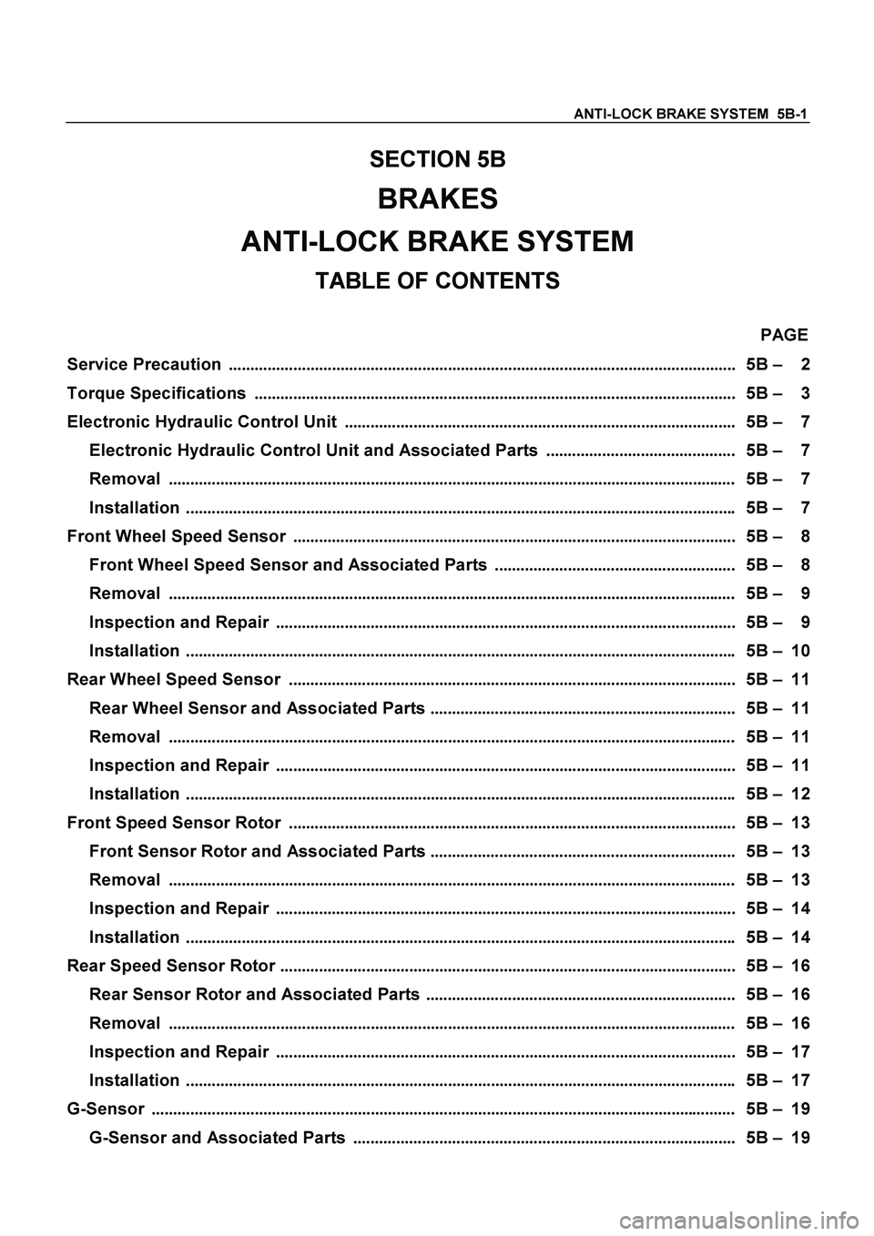
ANTI-LOCK BRAKE SYSTEM 5B-1
SECTION 5B
BRAKES
ANTI-LOCK BRAKE SYSTEM
TABLE OF CONTENTS
PAGE
Service Precaution ...................................................................................................................... 5B – 2
Torque Specifications ................................................................................................................ 5B – 3
Electronic Hydraulic Control Unit ........................................................................................... 5B – 7
Electronic Hydraulic Control Unit and Associated Parts ............................................ 5B – 7
Removal .................................................................................................................................... 5B – 7
Installation ................................................................................................................................ 5B – 7
Front Wheel Speed Sensor ....................................................................................................... 5B – 8
Front Wheel Speed Sensor and Associated Parts ........................................................ 5B – 8
Removal .................................................................................................................................... 5B – 9
Inspection and Repair ........................................................................................................... 5B – 9
Installation ................................................................................................................................ 5B – 10
Rear Wheel Speed Sensor ........................................................................................................ 5B – 11
Rear Wheel Sensor and Associated Parts ....................................................................... 5B – 11
Removal .................................................................................................................................... 5B – 11
Inspection and Repair ........................................................................................................... 5B – 11
Installation ................................................................................................................................ 5B – 12
Front Speed Sensor Rotor ........................................................................................................ 5B – 13
Front Sensor Rotor and Associated Parts ....................................................................... 5B – 13
Removal .................................................................................................................................... 5B – 13
Inspection and Repair ........................................................................................................... 5B – 14
Installation ................................................................................................................................ 5B – 14
Rear Speed Sensor Rotor .......................................................................................................... 5B – 16
Rear Sensor Rotor and Associated Parts ........................................................................ 5B – 16
Removal .................................................................................................................................... 5B – 16
Inspection and Repair ........................................................................................................... 5B – 17
Installation ................................................................................................................................ 5B – 17
G-Sensor ........................................................................................................................................ 5B – 19
G-Sensor and Associated Parts ......................................................................................... 5B – 19
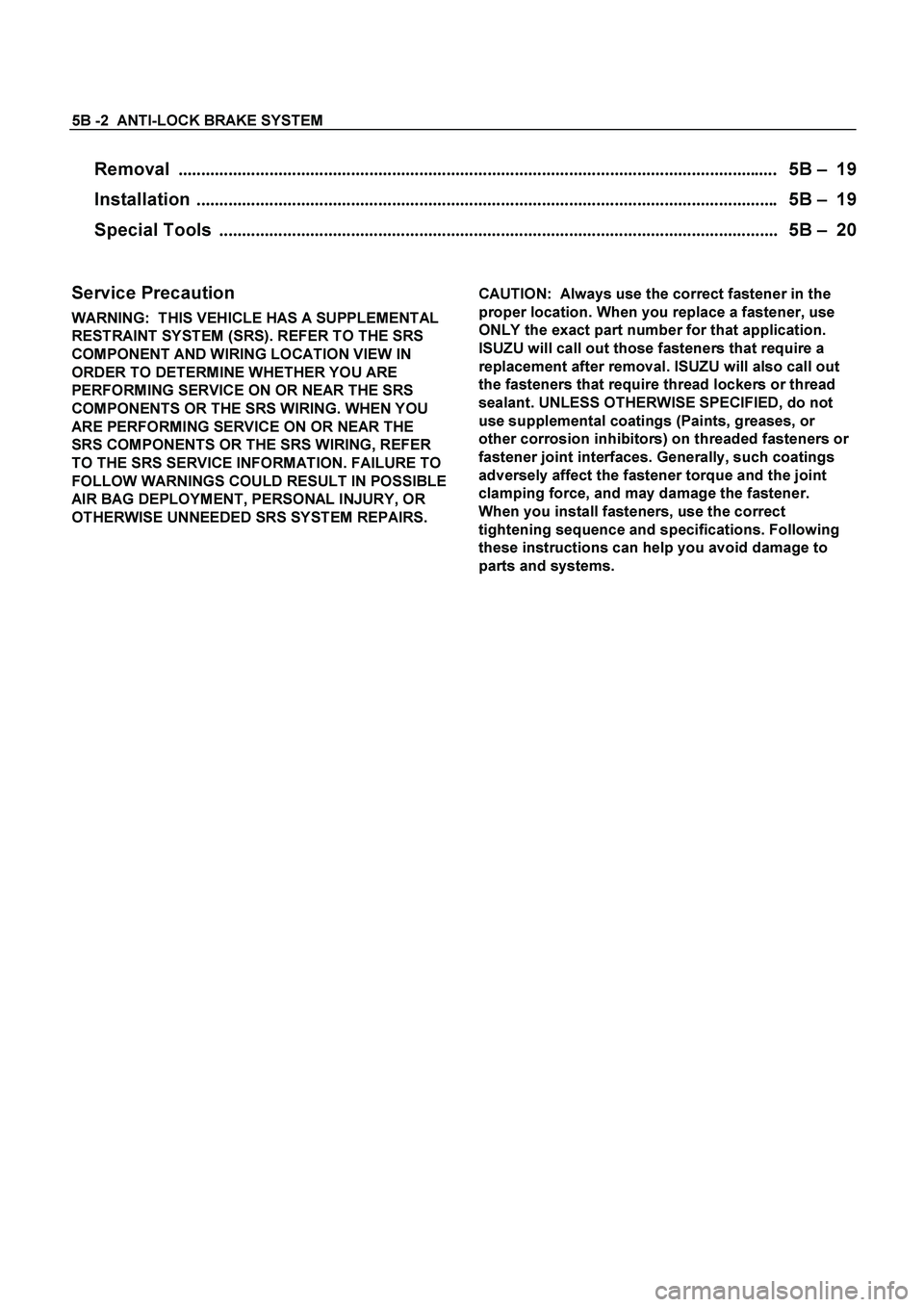
Page 408 of 4264

5B -2 ANTI-LOCK BRAKE SYSTEM
Removal .................................................................................................................................... 5B – 19
Installation ................................................................................................................................ 5B – 19
Special Tools ........................................................................................................................... 5B – 20
Service Precaution
WARNING: THIS VEHICLE HAS A SUPPLEMENTAL
RESTRAINT SYSTEM (SRS). REFER TO THE SRS
COMPONENT AND WIRING LOCATION VIEW IN
ORDER TO DETERMINE WHETHER YOU ARE
PERFORMING SERVICE ON OR NEAR THE SRS
COMPONENTS OR THE SRS WIRING. WHEN YOU
ARE PERFORMING SERVICE ON OR NEAR THE
SRS COMPONENTS OR THE SRS WIRING, REFER
TO THE SRS SERVICE INFORMATION. FAILURE TO
FOLLOW WARNINGS COULD RESULT IN POSSIBLE
AIR BAG DEPLOYMENT, PERSONAL INJURY, OR
OTHERWISE UNNEEDED SRS SYSTEM REPAIRS.
CAUTION: Always use the correct fastener in the
proper location. When you replace a fastener, use
ONLY the exact part number for that application.
ISUZU will call out those fasteners that require a
replacement after removal. ISUZU will also call out
the fasteners that require thread lockers or thread
sealant. UNLESS OTHERWISE SPECIFIED, do not
use supplemental coatings (Paints, greases, or
other corrosion inhibitors) on threaded fasteners or
fastener joint interfaces. Generally, such coatings
adversely affect the fastener torque and the joint
clamping force, and may damage the fastener.
When you install fasteners, use the correct
tightening sequence and specifications. Following
these instructions can help you avoid damage to
parts and systems.
Page 409 of 4264
ANTI-LOCK BRAKE SYSTEM 5B-3
Torque Specifications
Electronic Hydraulic Control Unit
This illustration is based
on RHD model
E05R300007
Page 410 of 4264
5B -4 ANTI-LOCK BRAKE SYSTEM
4�
�� �2 Front Speed Sensor
E05R300002
Page 411 of 4264
ANTI-LOCK BRAKE SYSTEM 5B-5
Front Speed Sensor (4�
�� �4, 4�
�� �2 High Ride)
E05R300003