Page 420 of 4264
5B -14 ANTI-LOCK BRAKE SYSTEM
411R300007
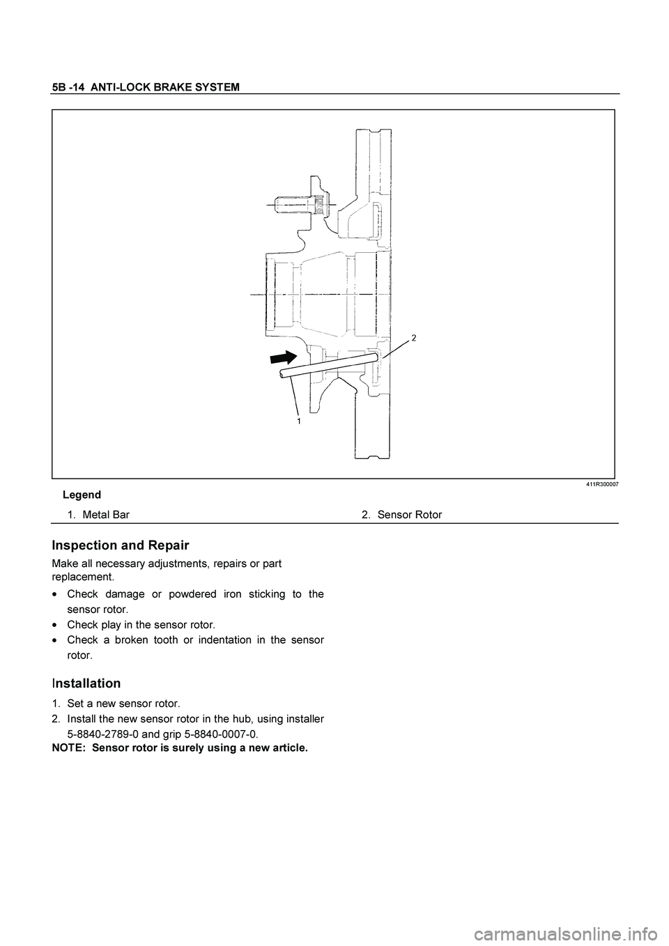
Legend
1.
Metal Bar
2.
Sensor Rotor
Inspection and Repair
Make all necessary adjustments, repairs or part
replacement.
�
Check damage or powdered iron sticking to the
sensor rotor.
�
Check play in the sensor rotor.
�
Check a broken tooth or indentation in the senso
r
rotor.
Installation
1. Set a new sensor rotor.
2. Install the new sensor rotor in the hub, using installe
r
5-8840-2789-0 and grip 5-8840-0007-0.
NOTE: Sensor rotor is surely using a new article.
Page 421 of 4264
ANTI-LOCK BRAKE SYSTEM 5B-15
411R300006
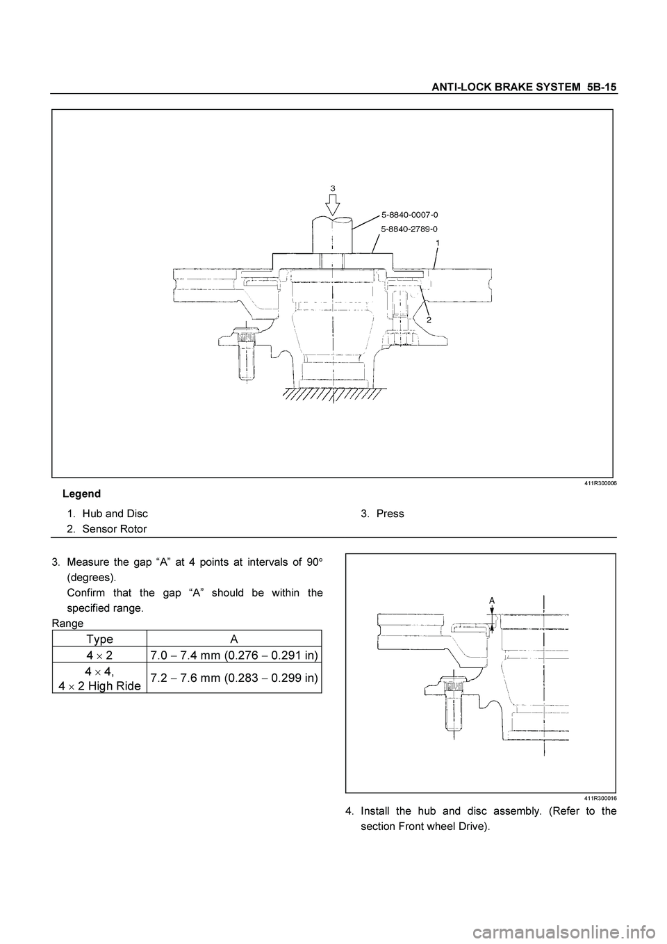
Legend
1.
Hub and Disc
2.
Sensor Rotor
3.
Press
3.
Measure the gap “A” at 4 points at intervals of 90�
(degrees).
Confirm that the gap “A” should be within the
specified range.
Range
Type A
4
�
2 7.0 �
7.4 mm (0.276 �
0.291 in)
4
�
4,
4
�
2 High Ride 7.2
� 7.6 mm (0.283
� 0.299 in)
411R300016
4. Install the hub and disc assembly. (Refer to the
section Front wheel Drive).
Page 422 of 4264
5B -16 ANTI-LOCK BRAKE SYSTEM
Rear Speed Sensor Rotor
Rear Sensor Rotor and Associated Parts
420R300007
Legend
1.
Axle Shaft Assembly with Brake
2.
Sensor Rotor
3.
Front
Removal
1. Remove the axle shaft assembly with brake (1).
(Refer to the section Rear Axle)
Page 423 of 4264
ANTI-LOCK BRAKE SYSTEM 5B-17
A03R300003
Legend
1.
Bench Press Fitting
2.
Steel Plate (25-30 mm thickness)
3.
Axle Shaft
4.
Sensor Rotor
Inspection and Repair
Make all necessary adjustments, repairs or part
replacement.
�
Check damage or powdered iron sticking to the
sensor rotor.
�
Check play in the sensor rotor.
�
Check a broken tooth or indentation in the senso
r
rotor.
NOTE: If replacement is required remove the sensor
rotor from the axle shaft assembly with brake. (Refer to
the section Rear Axle).
�
Discard the used sensor rotor.
(Snapring, Oil seal and Bearing)
Installation
1. Install the sensor rotor and assemble it into the axle
shaft assembly with back plate. (Refer to the section
Rear Axle)
Page 424 of 4264
5B -18 ANTI-LOCK BRAKE SYSTEM
420R300005
Legend
1.
Axle Shaft
2.
Oil Seal
3.
Bolt
4.
Back Plate
5.
Sensor Rotor
6.
Double Taper Roller Bearing
2. Install the axle shaft assembly with brake in the rea
r
axle. (Refer to the section Rear Axle).
Page 425 of 4264
ANTI-LOCK BRAKE SYSTEM 5B-19
G-Sensor
G-Sensor and Associated Parts
RTW45BLF000101
Legend
1.
G-Sensor
2.
Nut
Removal
1. Remove the front floor console. (Refer to the section
Floor Console)
2. Disconnect the connector.
3. Remove the nuts.
4. Take out the G-sensor.
Installation
1. Set the G-sensor.
2. Install the nut and tighten it to specified torque.
Torque : 8.0 N·m (0.8 kg·m /69 lb in)
3. Connect the connector.
4.
Install the front floor console. (Refer to the
section Floor Console)
Page 426 of 4264
5B -20 ANTI-LOCK BRAKE SYSTEM
Special Tools
ILLUSTRATION PART NO.
PART NAME
ILLUSTRATION
PART NO.
PART NAME
5–8840–2789–0
Installer ; Sensor rotor,
front hub 9-8522-1271-0
Setting Tool
5-8840-0007-0
Grip
Page 450 of 4264
 Rear wheel cylinder fluid pressure measurement
Step on the brake pedal until the fluid pressure of the
front wheel cylinder gets to 9.8Mpa (100kg/cm
2), and
c")
5C-24 BRAKES
RTW35CSH000201
3) Rear wheel cylinder fluid pressure measurement
Step on the brake pedal until the fluid pressure of the
front wheel cylinder gets to 9.8Mpa (100kg/cm
2), and
check the rear wheel cylinder fluid pressure. (Read the
value of the front wheel cylinder fluid pressure 2
seconds after the measurement. When measuring the
L.S.V fluid pressure, keep the brake pedal pressed
down without stepping it down twice or releasing it.)
Rear Wheel Cylinder Fluid Pressure MPa (kg/cm
2)
2WD 6.77�0.83 (69.0�8.5)
2WD (With High Ride
Suspension), 4WD 6.77�
0.83 (69.0�
8.5)
RTW35CSH000401
2. Oil Pressure Adjustment
1) LSPV spring length adjustment
Loosen the adjust nut of the LSPV spring joint, and
adjust the length of the LSPV spring.
When the oil pressure is insufficient, turn the adjust nu
t
clockwise to extend the span “A”. When the oil pressure
is too high, turn the adjust nut counterclockwise to
reduce the span “A”.
2) After adjustment, tighten the lock nut securely.
Lock Nut Torque N�m (kg�m/lb in)
11-20 (1.1-2.0/95-174)


3.
Axle Shaft
4.
Sensor Rotor
Inspection and Repair
Make all necess")


