Page 533 of 4264
CAB 10-25
REASSEMBLY
RTW3A0LF000701
Reassembly Steps
1. Anti rattler
2. Door harness assembly
� 3. Outside handle
4. Window glass
5. Glass run
6. Door lock assembly
7. Glass run rear channel
8. Window regulator/Power window regulator
9. Outer waste seal
10. Inside lever
11. Waterproof sheet
12. Speaker assembly
13. Bracket
14. Door trim panel
15. Bezel
16. Power window switch
� 17. Switch bezel/Window regulator handle
Page 537 of 4264
CAB 10-29
Important Operations
1. Front Console Assembly
�
Refer to Floor Consol in this section.
2. Glove Box
�
Remove 2 fixing screws and pulling the handle.
3. Instrument Panel Driver Lower Cover Assembly
1) Remove the engine hood opener 2 fixing screws.
2) Remove the lower cover one fixing screw.
3) Pull out the cover (Stick type parking brake only).
4) Pull out the lower cover assembly.
4. Driver Knee Bolster Assembly
�
Remove 4 fixing bolts.
Caution:
For precaution on installation or removal of SRS-air bag
system, refer to section 9 “Supplemental Restraint System
(SRS) - AIR BAG”
5. Driver Air Bag
6. Steering Wheel/Steering Cowl
�
Refer to Section 3B “STEERING COLUMN” for steering
lock assembly removal steps.
7. Meter Cluster Assembly
�
Pull out the 4 clip positions.
Page 539 of 4264
CAB 10-31
13.Ashtray Case
� Pull out the ashtray case.
14. Center Cluster Assembly
1) Pull out the cluster at the 6 clip positions.
2) Disconnect the cigarette lighter, accessory socket,
hazard switch and clock connectors.
15. Control Lever Assembly
�
Remove the 2 fixing screws.
17.Ashtray Bracket
�
Remove the 3 fixing screws and illumination connector.
Caution:
For precautions on installation or removal of SRS-air bag
system, refer to section 9 "Supplemental Restraint System
(SRS) - AIR BAG".
21. Passenger Air Bag
�
Remove 2 fixing bolts, 2 fixing nuts and connector.
22. Side Ventilation Grille.
� Pull out the grilles and disconnect switch connecto
r
(Driver’s side).
23. Vent Duct Assembly/Defroster Nozzle Assembly
�
Refer to section 1 “HVAC” for defroster nozzle and
ventilation duct removal steps.
25. Instrument Panel
�
Remove the clip and 6 fixing bolts.
26. Cross Beam
Page 567 of 4264
CAB 10-59
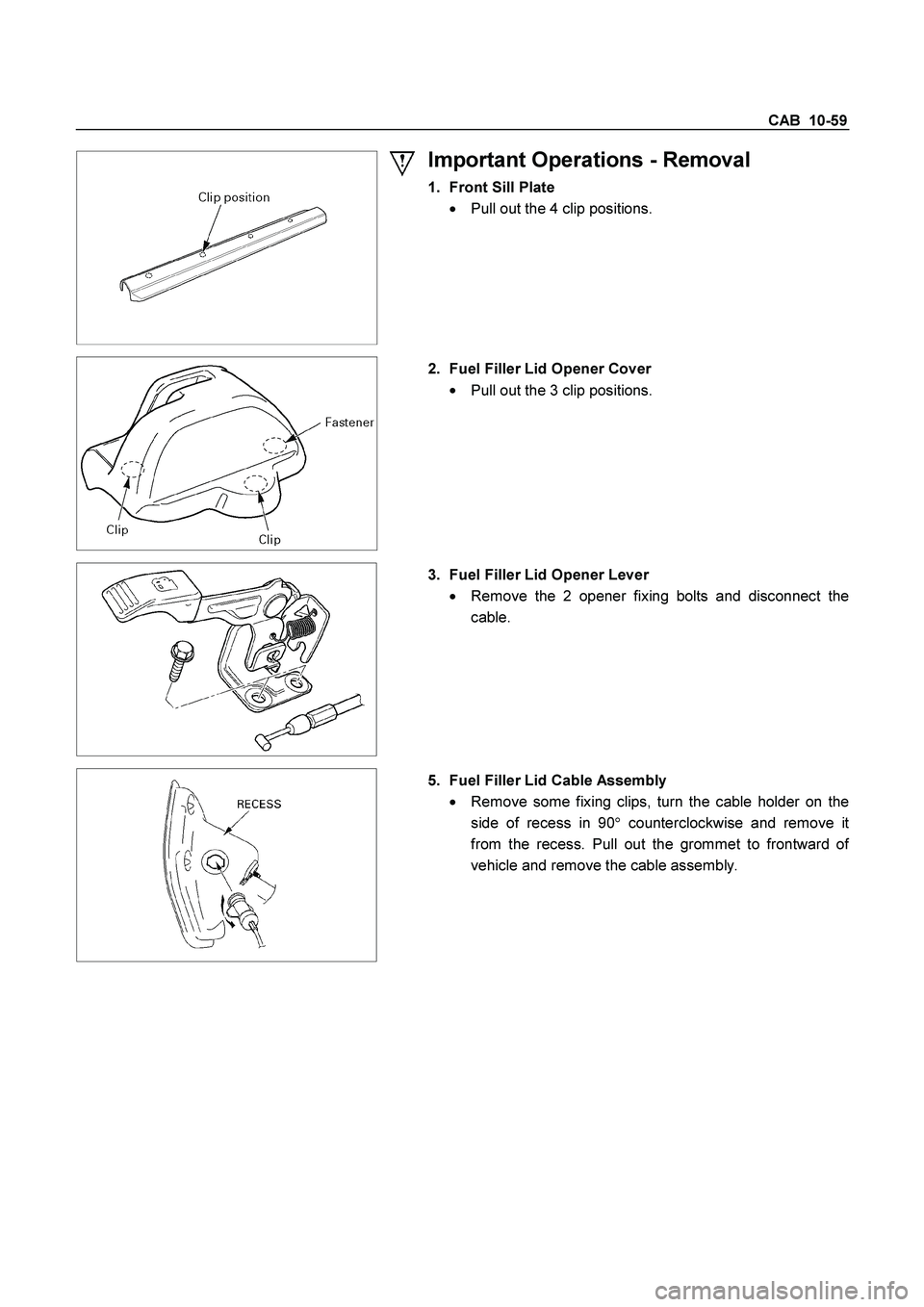
Important Operations - Removal
1. Front Sill Plate
�
Pull out the 4 clip positions.
2. Fuel Filler Lid Opener Cover
�
Pull out the 3 clip positions.
3. Fuel Filler Lid Opener Lever
�
Remove the 2 opener fixing bolts and disconnect the
cable.
5. Fuel Filler Lid Cable Assembly
�
Remove some fixing clips, turn the cable holder on the
side of recess in 90�counterclockwise and remove i
t
from the recess. Pull out the grommet to frontward o
f
vehicle and remove the cable assembly.
Page 570 of 4264
10-62 CAB
Important Operations - Removal
1. Front Sill Plate
�
Pull out 4 clip positions.
2. Rear Sill Plate
�
Pull out 2 clip positions.
4. Fuel Filler Lid Opener Cover
�
Pull out the 3 clip positions.
5. Fuel Filler Lid Opener Lever
�
Remove the 2 opener fixing bolts and disconnect the
cable.
7. Fuel Filler Lid Cable Assembly
�
Remove some fixing clips, turn the cable holder on the
side of recess in 90�counterclockwise and remove i
t
from the recess. Pull out the grommet to frontward o
f
vehicle and remove the cable assembly.
Page 582 of 4264
10-74 CAB
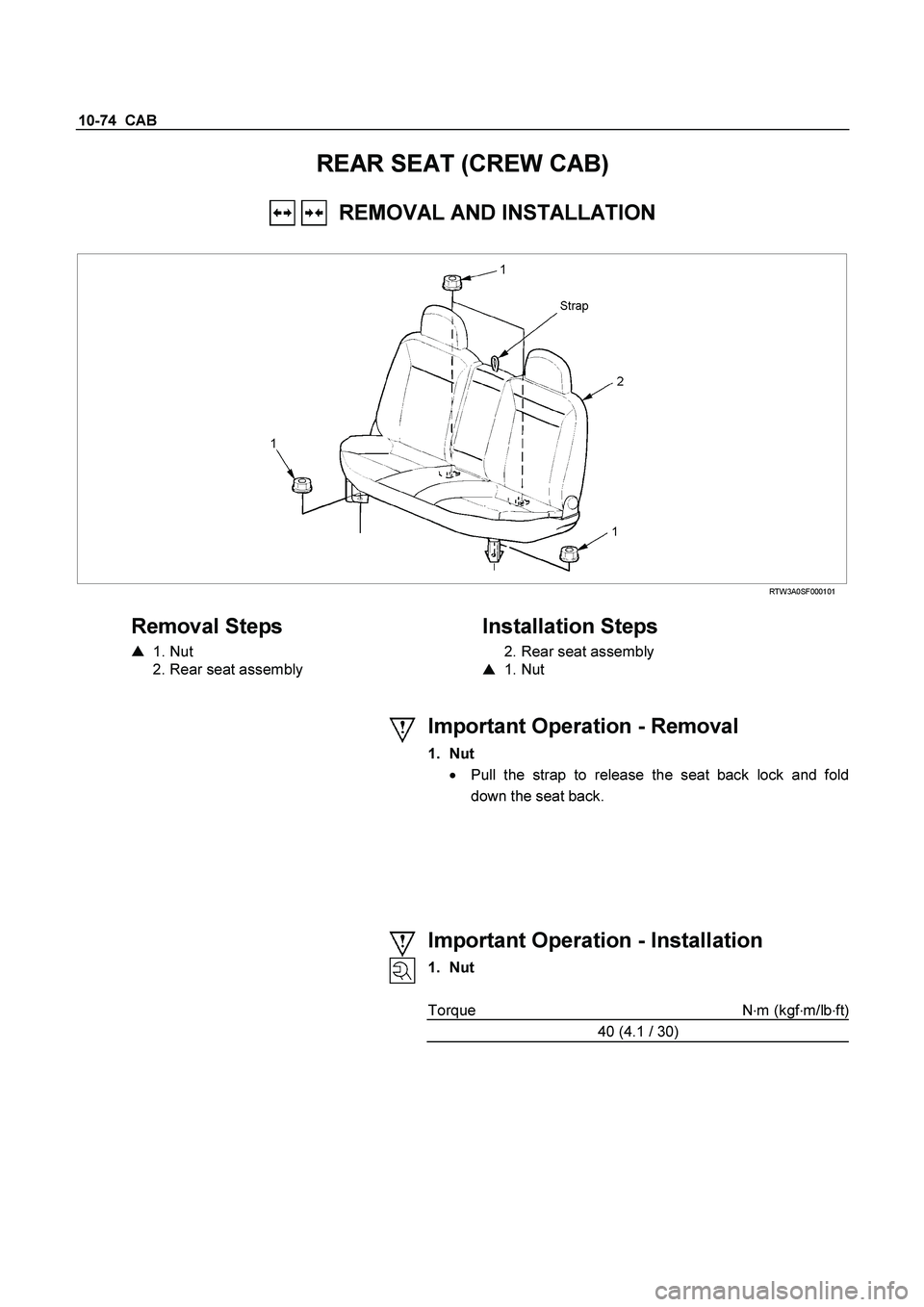
REAR SEAT (CREW CAB)
REMOVAL AND INSTALLATION
RTW3A0SF000101
Removal Steps
� 1. Nut
2. Rear seat assembly
Installation Steps
2. Rear seat assembly
� 1. Nut
Important Operation - Removal
1. Nut � Pull the strap to release the seat back lock and fold
down the seat back.
Important Operation - Installation
1. Nut
Torque N �
m (kgf �
m/lb �
ft)
40 (4.1 / 30)
Page 597 of 4264
CAB 10-89
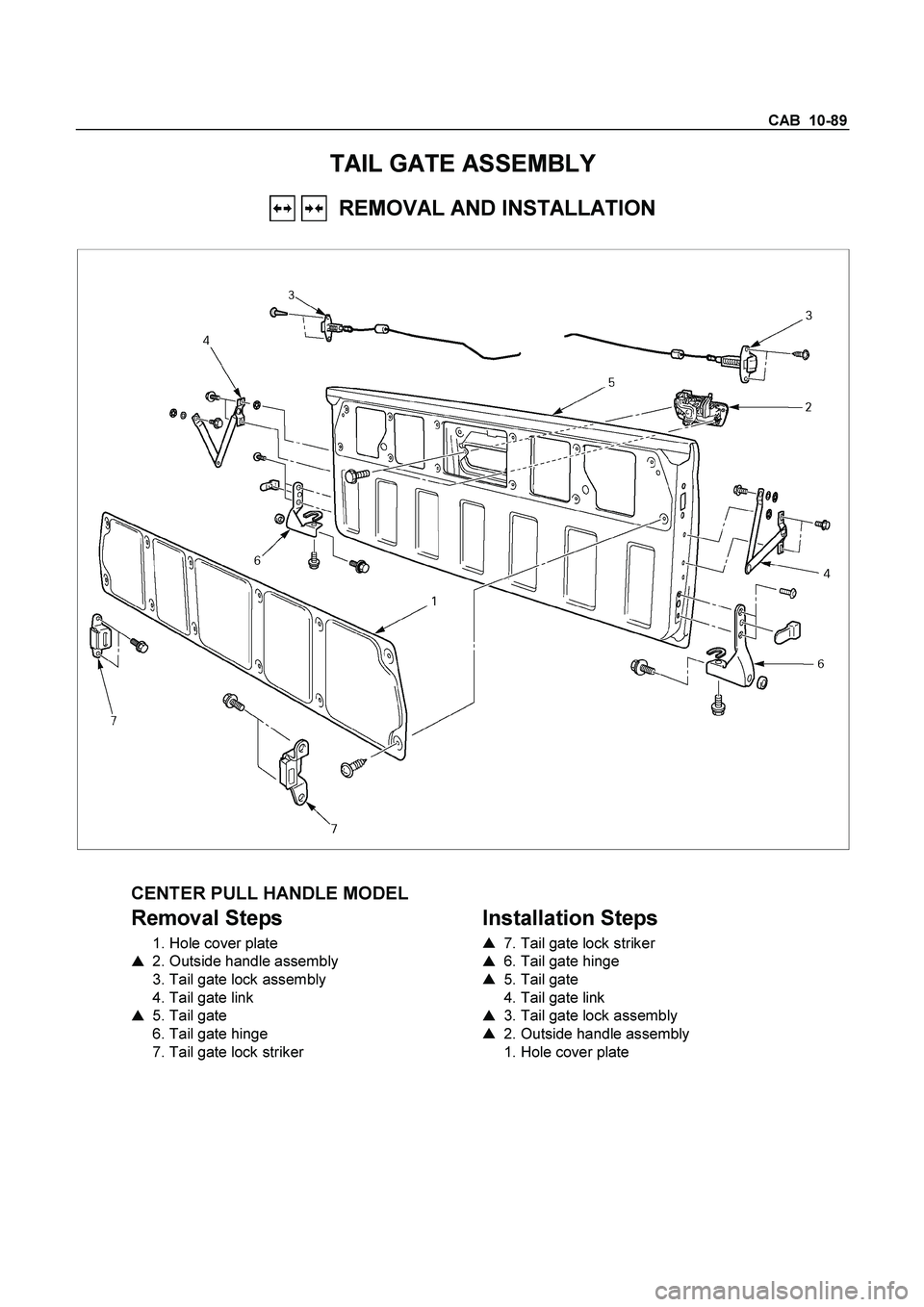
TAIL GATE ASSEMBLY
REMOVAL AND INSTALLATION
CENTER PULL HANDLE MODEL
Removal Steps
1. Hole cover plate
� 2. Outside handle assembly
3. Tail gate lock assembly
4. Tail gate link
� 5. Tail gate
6. Tail gate hinge
7. Tail gate lock striker
Installation Steps
�
7. Tail gate lock striker
� 6. Tail gate hinge
� 5. Tail gate
4. Tail gate link
� 3. Tail gate lock assembly
� 2. Outside handle assembly
1. Hole cover plate
Page 598 of 4264
 Removing the tailgate assembly may require")
10-90 CAB
Important Operations - Removal
2. Outside Handle Assembly
�
Disconnect the lock link and remove the 2 fixing bolts.
5. Tail Gate
1) Removing the tailgate assembly may require two people.
2) Remove the tailgate hinge fixing bolts.
Important Operations - Installation
7. Tail Gate Lock Striker
�
Tighten the lock striker fixing bolts to the specified
torque.
Torque N�m(kgf�m/lb�ft)
15 (1.5 / 11)
6. Tail Gate Hinge
�
Tighten the hinge fixing bolts to the specified torque.
C: Bolt
Torque N�m(kgf�m/lb�ft)
40 (4.1 / 30)
5. Tail Gate
1) A: Bolts
Torque N�
m(kgf�
m/lb�
in)
13 (1.3 / 113)
2) B: Bolt
Torque N�
m(kgf�
m/lb�
in)
25 (2.5 / 18)
3) Check the tailgate and rear body.
a. Clearance: 5.0 mm (0.20 in.)
b. Height (Step): Flush
c. Height (Step): Flush
3. Tail Gate Lock Assembly
�
Tighten the lock assembly fixing bolts to the specified
torque.
Torque N�
m(kgf�
m/lb�
ft)
15 (1.5 / 11)
2. Outside Handle Assembly
�
Tighten the outside handle assembly fixing bolts to the
specified torque and if remove the key cylinder (i
f
equipped) tighten it to the specified torque.
Torque N�
m(kgf�
m/lb�
in)
9 (0.9 / 78)