Page 698 of 4264
8A-40 ELECTRICAL-BODY AND CHASSIS
FUSE BLOCK CIRCUIT 4JA1-TC / 4JH1-TC (RHD) Sheet 2/2
RTW48AXF026801
Page 699 of 4264
ELECTRICAL-BODY AND CHASSIS 8A-41
FUSE BLOCK CIRCUIT 4JA1-TC / 4JH1-TC (LHD) Sheet 1/2
RTW48AXF000501
Page 700 of 4264
8A-42 ELECTRICAL-BODY AND CHASSIS
FUSE BLOCK CIRCUIT 4JA1-TC / 4JH1-TC (LHD) Sheet 2/2
RTW48AXF027001
Page 701 of 4264
ELECTRICAL-BODY AND CHASSIS 8A-43
FUSE BLOCK CIRCUIT 4JA1-L Sheet 1/2
RTW48AXF000801
Page 702 of 4264
8A-44 ELECTRICAL-BODY AND CHASSIS
FUSE BLOCK CIRCUIT 4JA1-L Sheet 2/2
RTW48AXF027101
Page 746 of 4264
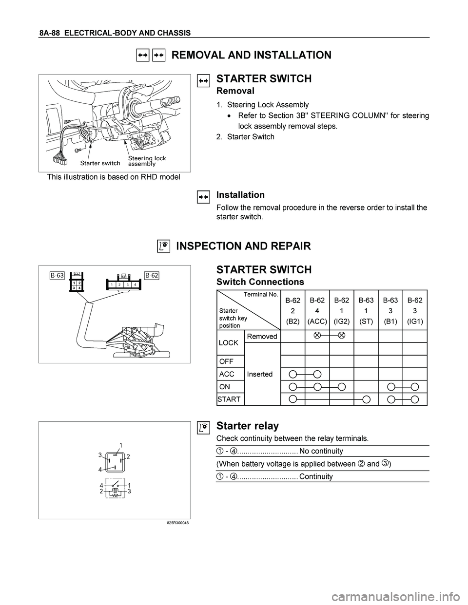
8A-88 ELECTRICAL-BODY AND CHASSIS
REMOVAL AND INSTALLATION
This illustration is based on RHD model
STARTER SWITCH
Removal
1. Steering Lock Assembly
� Refer to Section 3B" STEERING COLUMN" for steering
lock assembly removal steps.
2. Starter Switch
Installation
Follow the removal procedure in the reverse order to install the
starter switch.
INSPECTION AND REPAIR
STARTER SWITCH
Switch Connections
Terminal No.
Starter
switch key
position B-62
2
(B2)B-62
4
(ACC)B-62
1
(IG2) B-63
1
(ST) B-63
3
(B1)B-62
3
(IG1)
Removed
OFF
ACC Inserted
ON
START
LOCK
825R300046
Starter relay
Check continuity between the relay terminals.
1 - 4............................. No continuity
(When battery voltage is applied between 2 and 3)
1 - 4............................. Continuity
Page 763 of 4264
ELECTRICAL-BODY AND CHASSIS 8A-105
REMOVAL AND INSTALLATION
ECM (ENGINE CONTROL MODULE):
C24SE
Removal
1. Lift both the ECM harness connector locking levers and
remove the two harness connectors form the ECM.
2. Remove the four socket head screws securing the ECM to
the mounting bracket.
3. Remove the ECM from the engine compartment
.
4. Pull out the ECM.
5. Disconnect both red and tan connectors.
Refer to the Section 6E-ENGINE of this Manual.
IMPORTANT: The replacement ECM must be programmed.
“SPS (Service Programming System) and immobiliser
programming (if equipped) is/are necessary”
Installation
Follow the removal procedure in the reverse order to install the
ECM.
Pay close attention to the important points mentioned in the
following paragraphs.
Connector
Be absolutely sure that ECM is securely connected.
This will prevent a poor contact and open circuit.
Page 764 of 4264
8A-106 ELECTRICAL-BODY AND CHASSIS
REMOVAL AND INSTALLATION
ECM (ENGINE CONTROL MODULE):
6VE1
Removal
1. Pull both the red ECM harness connector locks toward the
front of the vehicle, and remove the two harness connectors
form the ECM.
2. Remove the four hex-head screws securing the ECM to the
common chamber.
3. Remove the ECM from the engine compartment.
4. Pull out the ECM.
5. Disconnect both red and tan connectors.
Refer to the Section 6E-ENGINE of this Manual.
IMPORTANT: The replacement ECM must be programmed.
“SPS (Service Programming System) and immobiliser
programming (if equipped) is/are necessary”
Installation
Follow the removal procedure in the reverse order to install the
ECM.
Pay close attention to the important points mentioned in the
following paragraphs.
Connector
Be absolutely sure that ECM is securely connected.
This will prevent a poor contact and open circuit.
 Sheet 2/2
RTW48AXF026801")
 Sheet 1/2
RTW48AXF000501")
 Sheet 2/2
RTW48AXF027001")


:
C24SE
Removal
1. Lift both the ECM harness connector locking levers and
remove the two harness")
:
6VE1
Removal
1. Pull both the red ECM harness connector locks toward the
front of the vehicle, an")