Page 664 of 4264

8A-6 ELECTRICAL-BODY AND CHASSIS
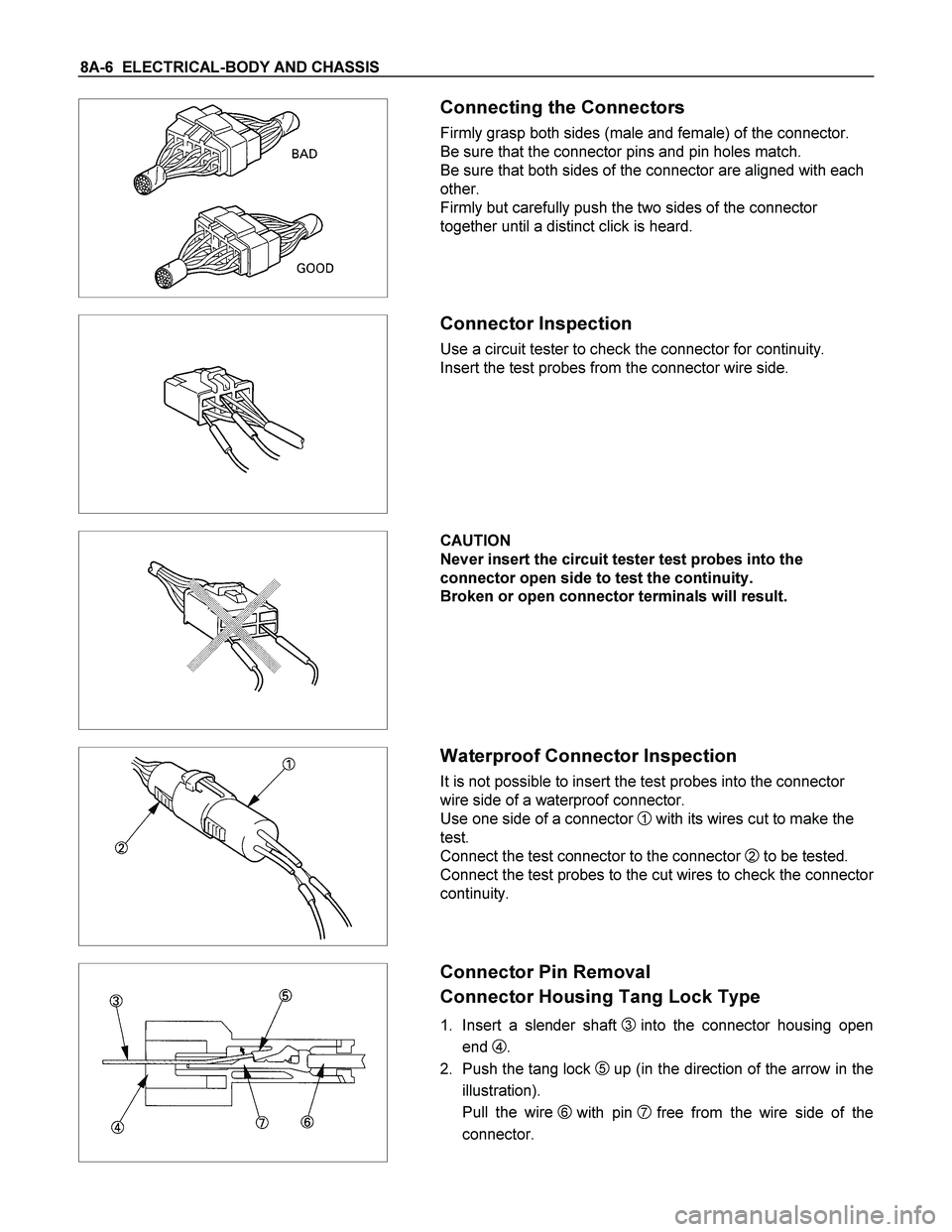
Connecting the Connectors
Firmly grasp both sides (male and female) of the connector.
Be sure that the connector pins and pin holes match.
Be sure that both sides of the connector are aligned with each
other.
Firmly but carefully push the two sides of the connector
together until a distinct click is heard.
Connector Inspection
Use a circuit tester to check the connector for continuity.
Insert the test probes from the connector wire side.
CAUTION
Never insert the circuit tester test probes into the
connector open side to test the continuity.
Broken or open connector terminals will result.
Waterproof Connector Inspection
It is not possible to insert the test probes into the connector
wire side of a waterproof connector.
Use one side of a connector
1 with its wires cut to make the
test.
Connect the test connector to the connector
2 to be tested.
Connect the test probes to the cut wires to check the connecto
r
continuity.
Connector Pin Removal
Connector Housing Tang Lock Type
1. Insert a slender shaft 3into the connector housing open
end
4.
2. Push the tang lock
5up (in the direction of the arrow in the
illustration).
Pull the wire
6 with pin 7free from the wire side of the
connector.
Page 665 of 4264

ELECTRICAL-BODY AND CHASSIS 8A-7
Pin Tang Lock Type
1. Insert a slender shaft 3 into the connector housing open
end
4.
2. Push the tang lock
8flat (toward the wire side of the
connector).
Pull the wire
6 with pin 7free from the wire side of the
connector.
Connector Pin Insertion
1. Check that the tang lock 8 is fully up.
2. Insert the pin
7 from the connector wire side 9.
Push the pin in until the tang lock closes firmly.
3. Gently pull on the wires
6to make sure that connector pin
is firmly set in place.
Fuse Replacement
The replacement fuse must have the same amperage
specification as the original fuse.
Never replace a burn out fuse with a fuse of a different
amperage specification.
Doing so can result in an electrical fire or other serious circuit
damage.
Parts Handling
Be careful for parts handling and any part should not be
dropped or thrown, otherwise short circuit or disorder may
result.
Wiring Harness
1. When assembling the parts, be careful not to bite or wedge
the wiring harness.
2. All electrical connections must be kept clean and tight.
Page 670 of 4264

8A-12 ELECTRICAL-BODY AND CHASSIS
ABBREVIATIONS
Abbreviation Meaning of abbreviation Abbreviation Meaning of abbreviation
A Ampere (S) LH Left hand
ABS Anti-lock brake system LWB Long wheel base
ASM Assembly MPI Multipart fuel injection
AC Alternating current M/T Manual transmission
A/C Air conditioner QOS Quick On Start system
ACC Accessories RH Right hand
CARB Carburetor RR Rear
C/B Circuit breaker RWAL Rear wheel anti-lock brake system
CSD Cold start device SRS Supplemental restraint system
DIS Direct ignition system ST Start
EBCM Electronic brake control module STD Standard
ECGI Electronic control gasoline injection SW Switch
ECM Engine control module SWB Short wheel base
ECU Electronic control unit TCM Transmission control module
EFE Early fuel evaporation V Volt
4�2 Two-wheel drive VSV Vacuum switching valve
4�4 Four-wheel drive W Watt (S)
FL Fusible link WOT Wide open throttle
FRT Front W/ With
H/L Headlight W/O Without
IC Integrated circuit
IG Ignition
kW Kilowatt
Page 693 of 4264
ELECTRICAL-BODY AND CHASSIS 8A-35
FUSE BLOCK CIRCUIT C24SE Sheet 1/2
RTW48AXF000101
Page 694 of 4264
8A-36 ELECTRICAL-BODY AND CHASSIS
FUSE BLOCK CIRCUIT C24SE Sheet 2/2
RTW48AXF026901
Page 695 of 4264
ELECTRICAL-BODY AND CHASSIS 8A-37
FUSE BLOCK CIRCUIT 6VE1 Sheet 1/2
RTW48AXF000301
Page 696 of 4264
8A-38 ELECTRICAL-BODY AND CHASSIS
FUSE BLOCK CIRCUIT 6VE1
Sheet 2/2
RTW48AXF026701
Page 697 of 4264
ELECTRICAL-BODY AND CHASSIS 8A-39
FUSE BLOCK CIRCUIT 4JA1-TC / 4JH1-TC (RHD) Sheet 1/2
RTW48AXF000401