Page 482 of 4264
5C-56 BRAKES
REASSEMBLY
Reassembly Steps
1. Secondary piston
2. Primary piston
3. Cylinder body
4. Grommet
5. Reservoir tank
6. Stop pin
7. Bolt
8. Snap ring
9. Diaphragm
10. Cap
1. Secondary piston
Lubricate the piston cups on the secondary piston assemblies
with brake fluid.
Note :
Be sure to use a new piston.
2. Primary piston
Lubricate the piston cups on the primary piston assemblies
with brake fluid (1) and the rubber grease (2).
Note :
Be sure to use a new piston.
Page 485 of 4264
BRAKES 5C-59
330R300002
Important Operation-Removal
1. Brake pipe
When hurdling, be careful not to spill brake fluid over the
painted surfaces, as damage to the paint finish will result.
2. Master Cylinder Fixing Nut
3. Bracket (only RHD model)
4. Master Cylinder Assembly
NOTE:
When removing the master cylinder from the vacuum booster,
be sure to get rid of the internal negative pressure of the
vacuum booster (by, for instance, disconnecting the vacuum
hose) in advance.
If any negative pressure remains in the vacuum booster, the
piston may possibly come out when the master cylinder is
being removed, letting the brake fluid run out.
While removing the master cylinder, further, do not hold the
piston as it can be easily pulled out.
Page 608 of 4264
7C-6 CLUTCH
6VE1/LHD
RTW47CSF000101
6VE1, 4J/RHD
RTW47CSF000401
The master cylinder converts mechanical energy into hydraulic energy.
Depressing the clutch pedal causes the push rod to move against the piston to close the return port.
Clutch fluid is forced out of the master cylinder.
Releasing the clutch pedal causes the return spring to force the piston back to its original position.
The return port is opened and the clutch fluid flows back into the fluid reservoir.
Quickly releasing the clutch pedal will cause the fluid pressure at the return spring side to be lower than the fluid
pressure at the push rod side.
This allows the fluid at the push rod side to quickly flow to the return spring side through a port in the piston head.
This equalizes the pressure at both sides of the piston.
Page 609 of 4264
CLUTCH 7C-7
SLAVE CYLINDER
6VE1
A07RS005
4J
C24SE
RTW47CSF000301
The slave cylinder converts hydraulic energy into mechanical energy.
Hydraulic fluid supplied by the master cylinder moves the slave cylinder piston to actuate the shift fork.
The mechanical energy produced by the slave cylinder is directly proportional to the diameters of the master
cylinder and the slave cylinder.
A bleeder screw is provided to bleed the slave cylinder.
Page 622 of 4264
7C-20 CLUTCH
AIR BLEEDING
Bleed air from clutch operating cylinder according to the
following procedure.
Carefully monitor fluid level at master cylinder during bleeding
operation.
1. Set the paking brake.
2. Top up reservoir with recommended brake fluid.
3. Connect a transparent vinyl tube to air bleeder valve.
4. Fully depress clutch pedal several times.
5. With clutch pedal depressed, open bleeder valve to release
air.
6. Close bleeder valve.
7. Repeat steps 5 through 6 above until brake fluid flows from
air bleeder valve without air bubbles.
8. Bleed air from clutch damper according to the above
procedure.
9. Repeat the above bleeding procedure until the air
completely removed.
Page 637 of 4264
CLUTCH 7C-35
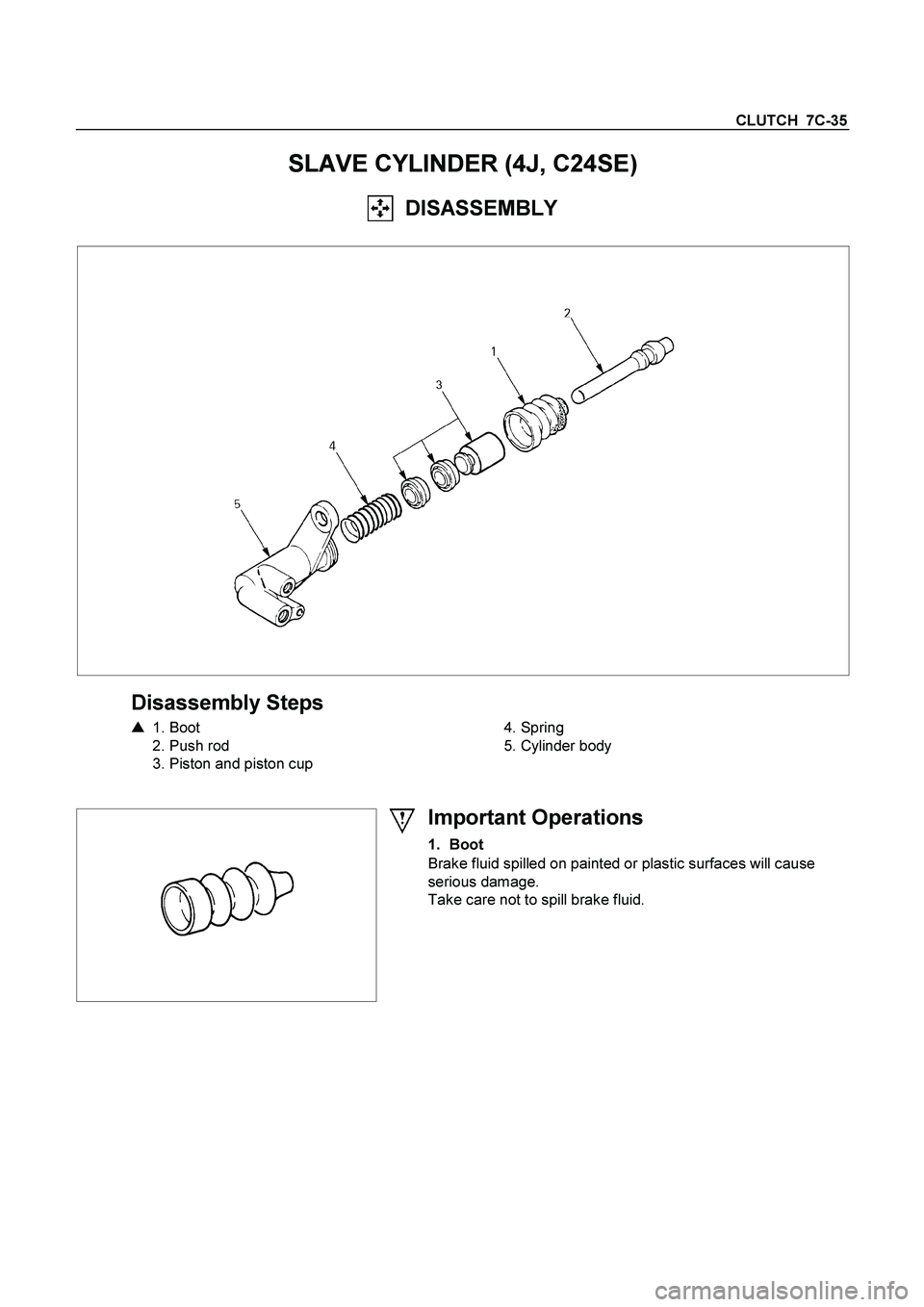
SLAVE CYLINDER (4J, C24SE)
DISASSEMBLY
Disassembly Steps
�
1. Boot
2. Push rod
3. Piston and piston cup
4. Spring
5. Cylinder body
Important Operations
1. Boot
Brake fluid spilled on painted or plastic surfaces will cause
serious damage.
Take care not to spill brake fluid.
Page 638 of 4264
7C-36 CLUTCH
INSPECTION AND REPAIR
Make the necessary adjustments, repairs, and part replacements if excessive wear or damage is discovered during
inspection.
Cylinder Body
1. Clean the cylinder body.
2. Check the fluid return port for restrictions and clean it i
f
necessary.
Cylinder Bore and piston Clearance
1. Clean the cylinder body and the piston.
2. Use an inside dial indicator to measure the cylinder bore.
3. Use a micrometer to measure the piston diameter.
4. Calculate the clearance between the cylinder bore and the
piston diameter.
If the clearance exceeds the limit, the entire slave cylinde
r
assembly must be replaced.
Cylinder Bore and Piston Clearance mm(in)
Standard Limit
0.07 (0.0028) 0.15 (0.006)
Piston and Piston Cup
Visually inspect the disassembled piston and piston cup for
excessive wear and damage.
Replace the inner parts with new parts (Repair kit A) shown in
the illustration.
Page 639 of 4264
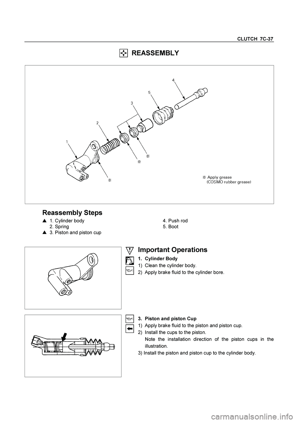
CLUTCH 7C-37
REASSEMBLY
Reassembly Steps
�
1. Cylinder body
2. Spring
�
3. Piston and piston cup
4. Push rod
5. Boot
Important Operations
1. Cylinder Body
1) Clean the cylinder body.
2) Apply brake fluid to the cylinder bore.
3. Piston and piston Cup
1) Apply brake fluid to the piston and piston cup.
2) Install the cups to the piston.
Note the installation direction of the piston cups in the
illustration.
3) Install the piston and piston cup to the cylinder body.