Page 641 of 4264
CLUTCH 7C-39
INSPECTION AND REPAIR
Make the necessary adjustments, repairs, and part replacements if excessive wear or damage is discovered during
inspection.
206RS003
Cylinder Body
1. Clean the cylinder body.
2. Check the fluid return port for restrictions and clean it i
f
necessary.
206RS004
Piston and Piston Cup
1. Visually inspect the disassembled piston and piston cup for
excessive wear and damage.
2. Replace the inner parts with new parts shown in the
illustration.
206RS005
3. Measure the clearance between slave cylinder wall and
piston.
4. If the measured value exceeds the specified limit, the slave
cylinder assembly must be replaced.
mm(in)
Standard Limit
0.07 (0.0028) 0.15 (0.006)
Page 652 of 4264
7C-50 CLUTCH
5. OIL LEAKAGE
Checkpoint
Trouble Cause
Countermeasure
Replace the body sub
assembly
Weak or damaged piston cup
NG
Tighten the oil pipe
Tighten the oil pipe connection
Tighten the fluid pipe and/or
hose connections
Fluid reservoir
Loosely connected oil pipe
Loosely connected oil pipe
Master cylinder fluid pipe and
hose
Loosely connected fluid pipe
and/or hose
Slave cylinder oil pipe
Replace the piston cup
Slave cylinder
Weak or damaged piston cup
NG NG NG NG
OK OK
OK
OK
Master cylinder
Page 919 of 4264

ELECTRICAL-BODY AND CHASSIS 8A-261
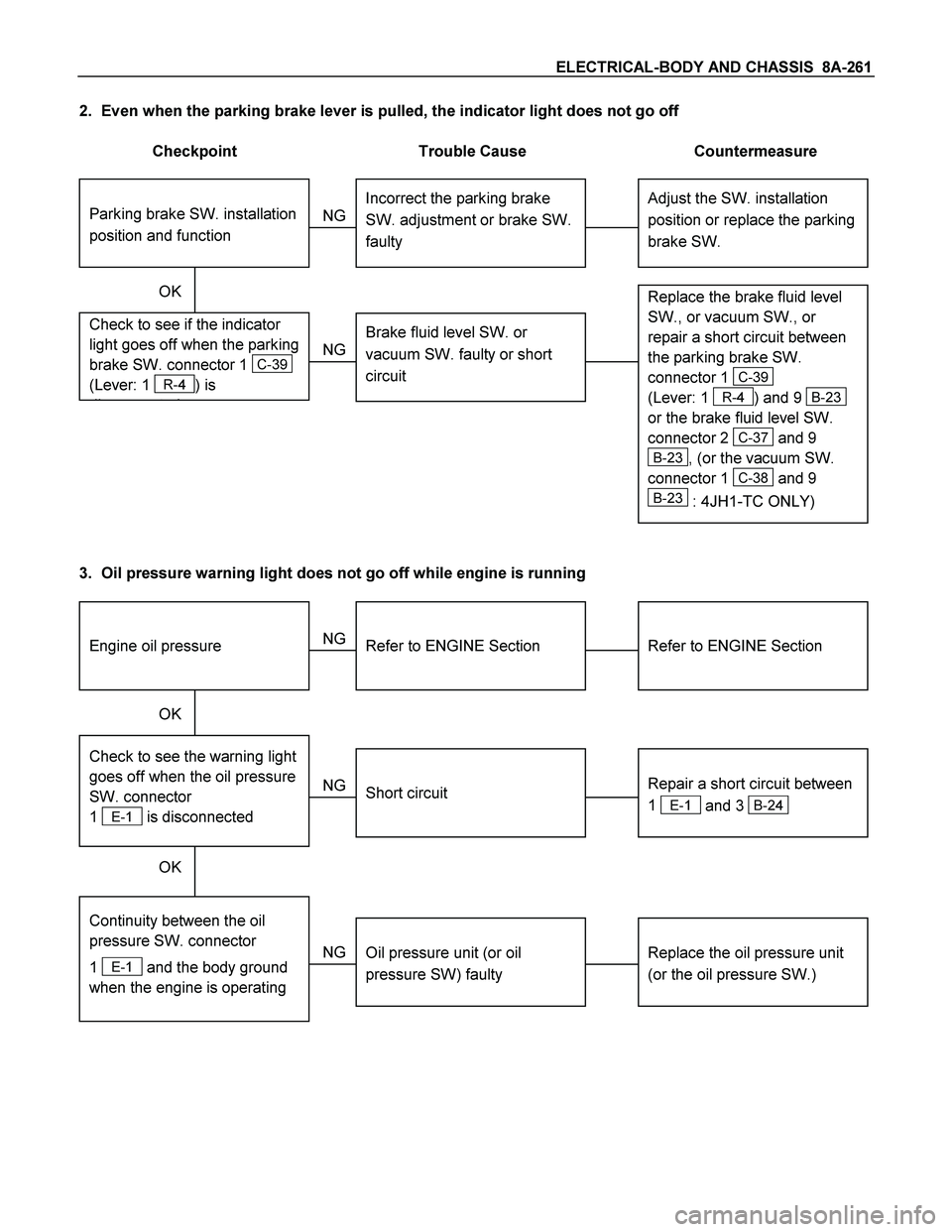
2. Even when the parking brake lever is pulled, the indicator light does not go off
Checkpoint Trouble Cause Countermeasure
Adjust the SW. installation
position or replace the parking
brake SW. Incorrect the parking brake
SW. adjustment or brake SW.
faulty
NG Thermo unit malfunction
Replace the brake fluid level
SW., or vacuum SW., or
repair a short circuit between
the parking brake SW.
connector 1
C-39
(Lever: 1
R-4) and 9 B-23
or the brake fluid level SW.
connector 2
C-37 and 9
B-23, (or the vacuum SW.
connector 1
C-38 and 9
B-23 : 4JH1-TC ONLY)
Check to see if the indicator
light goes off when the parking
brake SW. connector 1
C-39
(Lever: 1
R-4) is
di t d
Brake fluid level SW. or
vacuum SW. faulty or short
circuit
NG OK
Parking brake SW. installation
position and function
3. Oil pressure warning light does not go off while engine is running
Refer to ENGINE Section
Refer to ENGINE Section
NG Thermo unit malfunction
Repair a short circuit between
1
E-1 and 3 B-24
Check to see the warning light
goes off when the oil pressure
SW. connector
1
E-1 is disconnected
Short circuit
Replace the oil pressure unit
(or the oil pressure SW.)
Continuity between the oil
pressure SW. connector
1
E-1 and the body ground
when the engine is operating
Oil pressure unit (or oil
pressure SW) faulty
NG NG OK
OK
Engine oil pressure
Page 936 of 4264

8A-278 ELECTRICAL-BODY AND CHASSIS
Low Fuel Indicator Light Inspection
1. Disconnect the fuel tank unit wire connector.
2. Turn the key switch on. Check that the bulb lights.
If operation is not correct, remove and check the bulb or circuit.
or If check whether low fuel turns on fuel input (B-24) at the
time of open and key on.
� meter is check at low fuel
140R300006
Check level sensor operation
1. Remove the fuel tank unit.
2.
Apply battery voltage between terminal (B) and (C) through
a 1.12 watt bulb. Check that the bulb lights.
Note:
It will take a short time for the bulb light.
3. Submerge the sensor in fuel. Check that the bulb goes out.
If operation is not correct, replace the fuel tank unit.
BRAKE SYSTEM WARNING LIGHT
The brake system warning light comes on while the parking
brake is set and the engine run position.
Note:
The parking brake indicator light circuit is designed to
prevent driving of the vehicle with the parking brake on.
It does not indicate the condition of the parking brake
system.
The parking brake switch is in parallel with the brake fluid
switch.
The brake system warning light also comes on when reservoir
brake fluid level falls below the specified limit with the parking
brake released and the engine run position.
Page 1081 of 4264
ELECTRICAL-BODY AND CHASSIS 8A-423
No. Connector face No. Connector face
C-36
Silver
Engine room-LH ; Ground C-54
(6VE1)
(4JH1-TC)
OrangeABS sensor Front-LH
C-37
Black
Brake fluid level switch C-55
BrownThermo AMP
C-38
(4JH1-TC)
Vacuum switch C-56
(C24SE)
ECM
C-39
Parking brake switch (stick type) C-56
(4JA1-TC
4JH1-TC)
ECM-A
C-40
~
C-43 NOT USED C-57
(4JA1-TC
4JH1-TC)
ECM-B
C-44
White
Stop lamp switch C-58
~
C-62 NOT USED
C-45
~
C-49 NOT USED C-63
(6VE1)
(4JH1-TC)
Gray Front Fog lamp-RH
C-50
Condenser fan C-64
(6VE1)
(4JH1-TC)
Gray Front Fog lamp-LH
C-51
~
C-52 NOT USED C-65
~
C-66 NOT USED
C-53
(6VE1)
(4JH1-TC)
Orange ABS sensor Front-RH C-67
(6VE1)
(4JH1-TC)
BlackEHCU
Page 1122 of 4264

6 – 2 TROUBLESHOOTING
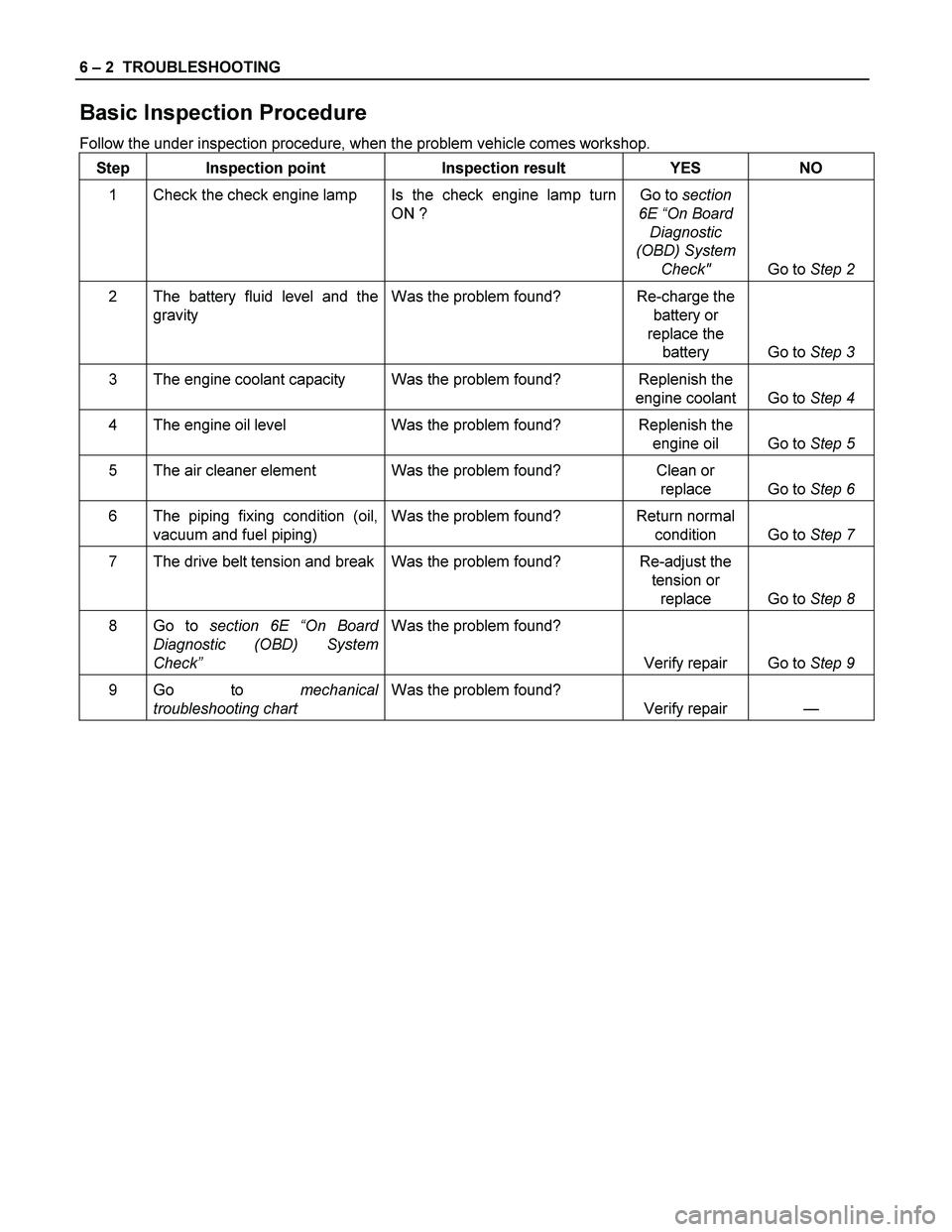
Basic Inspection Procedure
Follow the under inspection procedure, when the problem vehicle comes workshop.
Step Inspection point Inspection result YES NO
1 Check the check engine lamp Is the check engine lamp turn
ON ? Go to section
6E “On Board
Diagnostic
(OBD) System
Check" Go to Step 2
2 The battery fluid level and the
gravity Was the problem found? Re-charge the
battery or
replace the
battery Go to Step 3
3 The engine coolant capacity Was the problem found? Replenish the
engine coolant Go to Step 4
4 The engine oil level Was the problem found? Replenish the
engine oil Go to Step 5
5 The air cleaner element Was the problem found? Clean or
replace Go to Step 6
6 The piping fixing condition (oil,
vacuum and fuel piping) Was the problem found? Return normal
condition Go to Step 7
7 The drive belt tension and break Was the problem found? Re-adjust the
tension or
replace Go to Step 8
8 Go to section 6E “On Board
Diagnostic (OBD) System
Check” Was the problem found?
Verify repair Go to Step 9
9 Go to mechanical
troubleshooting chart Was the problem found?
Verify repair —
Page 1136 of 4264

6 – 16 TROUBLESHOOTING
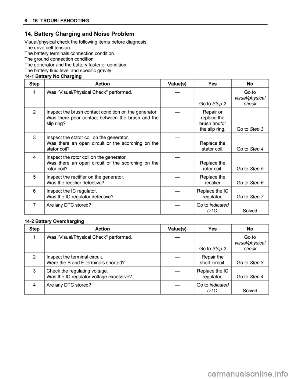
14. Battery Charging and Noise Problem
Visual/physical check the following items before diagnosis.
The drive belt tension.
The battery terminals connection condition.
The ground connection condition.
The generator and the battery fastener condition.
The battery fluid level and specific gravity.
14-1 Battery No Charging
Step Action Value(s) Yes No
1 Was “Visual/Physical Check" performed.
—
Go to Step 2 Go to
visual/physical
check
2 Inspect the brush contact condition on the generator.
Was there poor contact between the brush and the
slip ring? — Repair or
replace the
brush and/or
the slip ring. Go to Step 3
3 Inspect the stator coil on the generator.
Was there an open circuit or the scorching on the
stator coil? —
Replace the
stator coil. Go to Step 4
4 Inspect the rotor coil on the generator.
Was there an open circuit or the scorching on the
rotor coil? —
Replace the
rotor coil. Go to Step 5
5 Inspect the rectifier on the generator.
Was the rectifier defective? — Replace the
rectifier Go to Step 6
6 Inspect the IC regulator.
Was the IC regulator defective? — Replace the IC
regulator. Go to Step 7
7 Are any DTC stored? — Go to indicated
DTC. Solved
14-2 Battery Overcharging
Step Action Value(s) Yes No
1 Was “Visual/Physical Check" performed.
—
Go to Step 2 Go to
visual/physical
check
2 Inspect the terminal circuit.
Were the B and F terminals shorted? — Repair the
short circuit. Go to Step 3
3 Check the regulating voltage.
Was the IC regulator voltage excessive? — Replace the IC
regulator. Go to Step 4
4 Are any DTC stored? — Go to indicated
DTC. Solved
Page 1139 of 4264

TROUBLESHOOTING 6 – 19
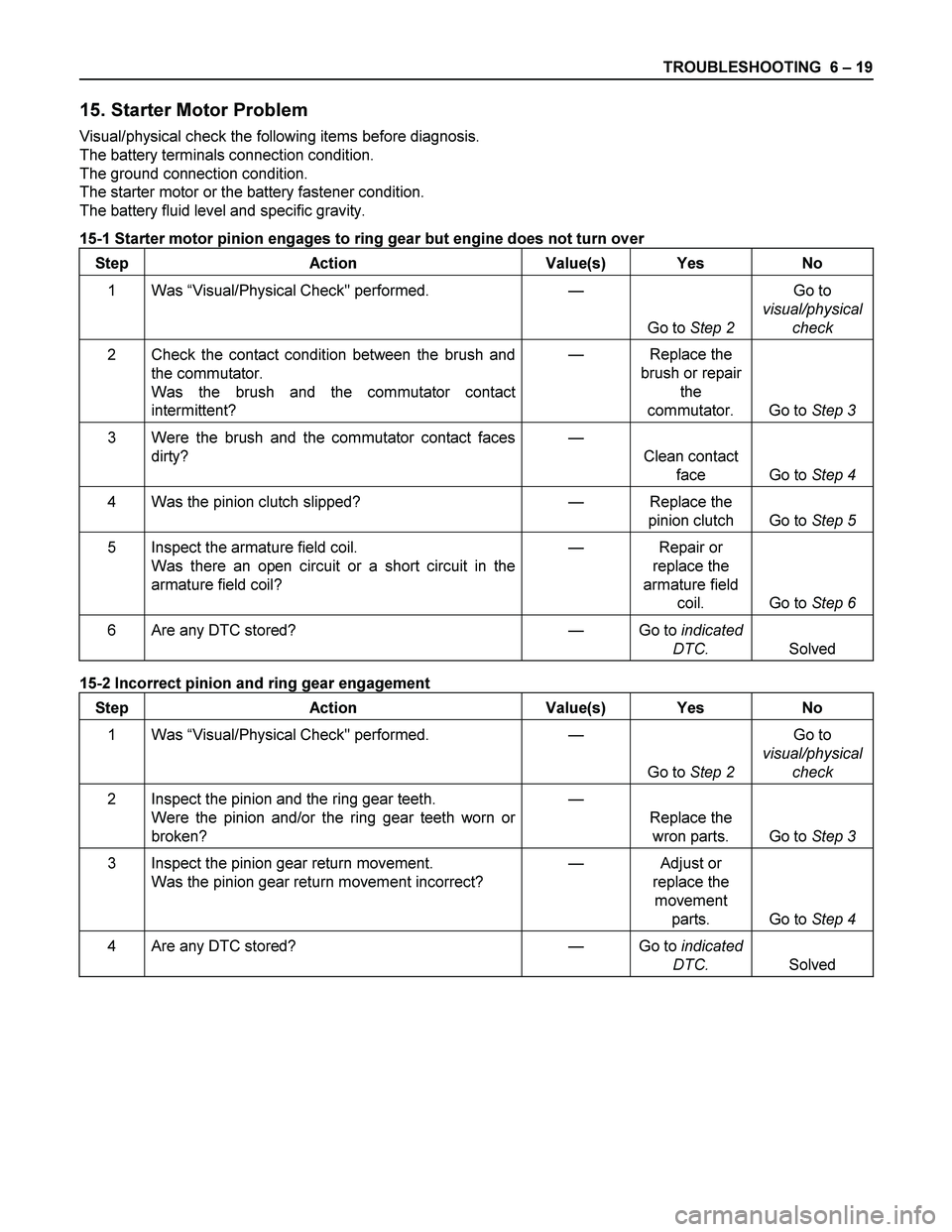
15. Starter Motor Problem
Visual/physical check the following items before diagnosis.
The battery terminals connection condition.
The ground connection condition.
The starter motor or the battery fastener condition.
The battery fluid level and specific gravity.
15-1 Starter motor pinion engages to ring gear but engine does not turn over
Step Action Value(s) Yes No
1 Was “Visual/Physical Check" performed.
—
Go to Step 2 Go to
visual/physical
check
2 Check the contact condition between the brush and
the commutator.
Was the brush and the commutator contact
intermittent? — Replace the
brush or repair
the
commutator. Go to Step 3
3 Were the brush and the commutator contact faces
dirty?
—
Clean contact
face Go to Step 4
4 Was the pinion clutch slipped? — Replace the
pinion clutch Go to Step 5
5 Inspect the armature field coil.
Was there an open circuit or a short circuit in the
armature field coil? — Repair or
replace the
armature field
coil. Go to Step 6
6 Are any DTC stored? — Go to indicated
DTC. Solved
15-2 Incorrect pinion and ring gear engagement
Step Action Value(s) Yes No
1 Was “Visual/Physical Check" performed.
—
Go to Step 2 Go to
visual/physical
check
2 Inspect the pinion and the ring gear teeth.
Were the pinion and/or the ring gear teeth worn or
broken? —
Replace the
wron parts. Go to Step 3
3 Inspect the pinion gear return movement.
Was the pinion gear return movement incorrect? — Adjust or
replace the
movement
parts. Go to Step 4
4 Are any DTC stored? — Go to indicated
DTC. Solved