Page 976 of 4264

8A-318 ELECTRICAL-BODY AND CHASSIS
Checkpoint Trouble Cause Countermeasure
Replace the driver seat side
power window & door lock
SW.
SW. malfunction OK
NGDriver seat side power window
& door lock SW. function
Continued from the previous page
2. Lock switch does not function
Checkpoint Trouble Cause Countermeasure
Replace the driver seat side
power window & door lock
SW.
SW. malfunction NGDriver seat side power window
& door lock SW. function
3. Window on the driver’s side does not operate
Checkpoint Trouble Cause Countermeasure
Replace the driver seat side
power window & door lock
SW.
SW. malfunction
NG
Replace the driver seat side
power window motor
Motor malfunction
NG OK
Driver seat side power window
& door lock SW. function
OK
Repair open circuit or
connector contact
Open circuit or poor connector
contact
NG Continuity between 7 D-5
and 1
D-1, or 8 D-5 and 2
D-1
1. Driver seat side power
window motor function
when connection the motor
connector 1
D-1 to the
battery (+) terminal, and 2
D-1 to the (-) terminal
(Should the motor rotate in
the “UP” direction of the
window)
2. Driver seat side power
window motor function
when connecting the motor
connector 2
D-1 to the
battery (+) terminal, and 1
D-1 to the (-) terminal
(Should the motor rotate in
the “DOWN” direction of the
window)
Page 977 of 4264

Removal
1. Disconnect t")
ELECTRICAL-BODY AND CHASSIS 8A-319
REMOVAL AND INSTALLATION
This photo is based on RHD
DRIVER SEAT SIDE POWER WINDOW &
DOOR LOCK SWITCH
(2 DOORS MODEL)
Removal
1. Disconnect the battery ground cable.
2. Removes the screw in pull cup with the tip of a screwdriver.
3. Remove the switch bezel by pushing the spring with the tip
of a screwdriver.
4. Disconnect the connector.
ATTENTION:
When removing a switch bezel lift from the front in the
bezel.
It follows the front with the screwdriver.
The clip has broken when lifting from the rear in the bezel.
Installation
To install, follow the removal steps in the reverse order.
This photo is based on RHD
FRONT PASSENGER’S POWER WINDOW
& DOOR LOCK SWITCH
(2 DOORS MODEL)
Removal
1. Disconnect the battery ground cable.
2. Removes the screw in pull cup with the tip of a screwdriver.
3. Remove the switch bezel by pushing the spring with the tip
of a screwdriver.
4. Disconnect the connector.
ATTENTION:
When removing a switch bezel lift from the front in the
bezel.
It follows the front with the screwdriver.
The clip has broken when lifting from the rear in the bezel.
Installation
To install, follow the removal steps in the reverse order.
Page 978 of 4264

Removal
1. Disconnect the battery ground cable.
2. Removes the")
8A-320 ELECTRICAL-BODY AND CHASSIS
This photo is based on RHD
DRIVER SEAT SIDE POWER WINDOW &
DOOR LOCK SWITCH
(4 DOORS MODEL)
Removal
1. Disconnect the battery ground cable.
2. Removes the screw in pull cup with the tip of a screwdriver.
3. Remove the switch bezel by pushing the spring with the tip
of a screwdriver.
4. Disconnect the connector.
ATTENTION:
When removing a switch bezel lift from the front in the
bezel.
It follows the front with the screwdriver.
The clip has broken when lifting from the rear in the bezel.
Installation
To install, follow the removal steps in the reverse order.
This photo is based on RHD
FRONT PASSENGER’S POWER WINDOW
& DOOR LOCK SWITCH
(4 DOORS MODEL)
Removal
1. Disconnect the battery ground cable.
2. Removes the screw in pull cup with the tip of a screwdriver.
3. Remove the switch bezel by pushing the spring with the tip
of a screwdriver.
4. Disconnect the connector.
ATTENTION:
When removing a switch bezel lift from the front in the
bezel.
It follows the front with the screwdriver.
The clip has broken when lifting from the rear in the bezel.
Installation
To install, follow the removal steps in the reverse order.
REAR POWER WINDOW & DOOR LOCK
SWITCH-LH & RH
Removal
1. Disconnect the battery ground cable.
2. Removes the screw in pull cup with the tip of a screwdriver.
3. Remove the switch bezel by pushing the spring with the tip
of a screwdriver.
4. Disconnect the connector.
ATTENTION:
When removing a switch bezel lift from the front in the
bezel.
It follows the front with the screwdriver.
The clip has broken when lifting from the rear in the bezel.
Page 981 of 4264

ELECTRICAL-BODY AND CHASSIS 8A-323
INSPECTION AND REPAIR
B-8
Power Window Relay
Check continuity between the relay terminals.
2- 1......................... No continuity
(When battery voltage is applied between
3 and 4)
2- 1......................... Continuity
Harness side
D-20 D-5
Driver Seat Side Power Window & Door Lock
Switch
1. Harness Side Connector Circuit
Disconnect the switch connector, and check voltage and
continuity between the harness side connector terminals as
shown in the following table.
Terminal
No. Wire
color Connecting to Check item Connectin
g terminal Check condition Standard
6 G/R Power window
relay Voltage 6-Ground Starter SW “ON” Approx.
12V
7 BR/R
Power window
8 BR/W motor
3 B Ground Continuity 3-Ground - Continuity
Harness side
D-10
Front Passenger’s Power Window & Door Lock
Switch
1. Harness Side Connector Circuit
Disconnect the switch connector, and check voltage and
continuity between the harness side connector terminals as
shown in the following table.
Continuity
- 7-8 Continuity
Page 983 of 4264
ELECTRICAL-BODY AND CHASSIS 8A-325
Harness side
D-5
Driver Seat Side Power Window Motor
1. Driver Seat Side Power Window & Door Lock Switch
Connector Circuit
Disconnect the switch connector, apply the battery voltage
(12V) to the harness side connector terminals and check
operation.
Connecting terminals
Operation
7 (BR/R) 8 (BR/W) direction
- + DOWN
+ - UP
2. Driver Seat Side Power Window Motor Connector
Circuit
Disconnect the switch connector, apply the battery voltage
(12V) to the motor side connector terminals and check
operation.
Connecting terminals
Operation
1 2 direction
+ - DOWN
- + UP
Page 984 of 4264
8A-326 ELECTRICAL-BODY AND CHASSIS
Harness side
D-10
Front Passenger’s Power Window Motor
1. Front Passenger’s Power Window Switch & Door Lock
Switch Connector Circuit
Disconnect the motor connector, apply the battery voltage
(12V) to the harness side connector terminals and check
operation.
Connecting terminals
Operation
12 (BR/R) 10 (BR/W) direction
- + DOWN
+ - UP
2. Front Passenger’s Power Window Motor Connector
Circuit
Disconnect the switch connector, apply the battery voltage
(12V) to the motor side connector terminals and check
operation.
Connecting terminals
Operation
1 2 direction
+ - DOWN
- + UP
Page 1054 of 4264
8A-396 ELECTRICAL-BODY AND CHASSIS
RTW38DLH000101
Menu
The left table shows witch functions are used for the
available equipment versions.
NOTE: Marked items are not applied for keyless entry
system.
DTC
On OBD has three options available in the Tech-2
DTC mode to display the enhanced information
available.
� Read DTC Info Ordered By Priority.
� Read DTC Info As Stored By ECU.
� Clear DTC and Alarm Code Info.
Clear DTC Information
To clear Diagnostic Trouble Codes (DTCs), Use the
diagnostic scan tool “Clear DTC Information” function.
Tech-2 Data Display
The Tech-2 data values represent values that would
be seen on a normally-keyless entry system.
RTW38DSH001601
Actuator Test
Unlock/Lock Test
Check whether opening and closing of a door lock
can be performed by operation of Tech-2.
1. Turn the key “OFF”.
2. Turn the key “ON”.
3. Check the display and test menu.
4. Operate the Tech-2.
Page 1078 of 4264
8A-420 ELECTRICAL-BODY AND CHASSIS
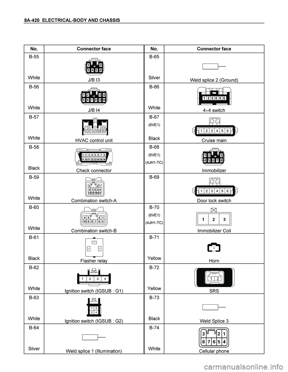
No. Connector face No. Connector face
B-55
White
J/B I3 B-65
SilverWeld splice 2 (Ground)
B-56
White
J/B I4 B-66
White4�4 switch
B-57
White
HVAC control unit B-67
(6VE1)
BlackCruise main
B-58
Black
Check connector B-68
(6VE1)
(4JH1-TC)
Immobilizer
B-59
White
Combination switch-A B-69
Door lock switch
B-60
White
Combination switch-B B-70
(6VE1)
(4JH1-TC)
Immobilizer Coil
B-61
Black
Flasher relay B-71
YellowHorn
B-62
White
Ignition switch (IGSUB : G1) B-72
YellowSRS
B-63
White
Ignition switch (IGSUB : G2) B-73
BlackWeld Splice 3
B-64
Silver
Weld splice 1 (Illumination) B-74
WhiteCellular phone